In 400V-class power supply filtering and coupling circuits, the 0.68µF film capacitor is one of the specifications frequently used by engineers at high frequencies.ECQ-E4684KZAs a classic model in this segment, with ±10% tolerance, polyester film dielectric, and radial lead package, it continues to maintain high shipment volumes in industrial power supplies, LED drivers, and home appliance control boards. Based on the latest technical documentation and measured data, this article systematically reviews seven key selection verification points for this model, helping engineers make quick decisions during replacement selection, cost-reduction design, and reliability assessment.
Model Positioning and Quick Overview of Core Parameters
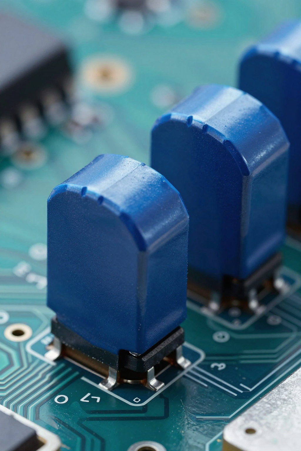
ECQ-E4684KZPart of Panasonic's ECQ-E series of metallized polyester film capacitors, this series is renowned for its high voltage ratings, wide capacitance range, and cost-effectiveness. The part number follows industry-standard conventions: "ECQ-E" denotes the series, "4684" corresponds to a 0.68 µF capacitance (68 × 10⁴ pF), "K" indicates a ±10% tolerance, and "Z" signifies a radial lead package.
ECQ-E4684KZ Naming Convention and Series Affiliation
Breaking down the model reveals key details: the E series employs a metallized polyester (PET) dielectric, distinguishing it from the ECQ-P series that uses polypropylene (PP). Polyester offers superior performance in terms of capacitance-to-volume ratio and cost efficiency, making it well-suited for general-purpose applications where extremely low loss is not critical. The "Z" suffix confirms a 15 mm lead spacing, adhering to standard radial packaging and compatible with automated insertion processes.
0.68µF/400V Key Electrical Parameters Overview
| Parameter Item | Specification Value | Test Conditions |
|---|---|---|
| Rated Capacitance | 0.68µF | 1kHz, 20℃ |
| Capacitance Tolerance | ±10% (Class K) | — |
| Rated Voltage | 400VDC | Continuous Operation |
| Withstand Voltage | 960VDC | 1 minute |
| Insulation Resistance | ≥15000MΩ | 100VDC, 60s |
| Dissipation Factor | ≤1.0% | 1kHz, 20℃ |
| Operating Temperature Range | -40℃~+105℃ | — |
| Lead Spacing | 15mm | — |
| Body Dimensions (L×W×H) | 18.0×7.5×14.5mm | Typical Value |
Dielectric Material Properties and Voltage Derating Analysis
The dielectric constant of polyester film is approximately 3.3, higher than that of polypropylene at 2.2, which makesECQ-E4684KZIt can achieve higher capacitance density at the same volume. However, this advantage comes at the cost of increased temperature sensitivity and losses, requiring careful evaluation under actual operating conditions.
Dielectric Properties and Temperature Coefficient of Polyester Film (PET)
The dielectric constant temperature coefficient of PET dielectric is approximately +200 ppm/°C. At the maximum operating temperature of +105°C, the capacitance increases by about 1.7% relative to the reference value at 20°C. This positive drift characteristic complements the negative temperature coefficient of ceramic capacitors; therefore, in wide-temperature filtering applications, the total deviation must be carefully calculated. Due to dielectric absorption effects, PET film exhibits approximately 0.2% charge retention, which should be avoided in precision integration circuits.
Derating Curve for Actual Operating Voltage at a Rated Voltage of 400 VDC
Industry best practices recommend that the continuous operating voltage of film capacitors not exceed 70%-80% of their rated value.ECQ-E4684KZUnder a 400VDC rated condition, it is recommended to keep the long-term operating voltage within the 280–320VDC range. In high-temperature environments, temperature derating must be applied: for every 10°C increase above +85°C, the voltage withstand capability decreases by approximately 8%. In pulse application scenarios, peak voltages may briefly reach the rated value; however, when the repetition frequency exceeds 1kHz, additional evaluation of dielectric heating is required.
Measured Data on Capacitance Accuracy and Temperature Stability
Assessment of the Impact of ±10% Tolerance on Filter Circuits
In RC filters, the K-grade tolerance of ±10% directly determines the range of cutoff frequency variation. Taking a typical low-pass filter composed of 2.2 kΩ and 0.68 µF as an example, the theoretical cutoff frequency is 106 Hz, while the actual distribution ranges from 96 to 117 Hz. For secondary-side ripple suppression in switch-mode power supplies, this deviation is usually acceptable; however, in PFC circuits, a lower capacitance limit can lead to insufficient energy storage, causing deterioration in current THD. It is recommended to select the J-grade version with ±5% accuracy for critical paths.
Capacity drift characteristics within the temperature range of -40°C to +105°C
Measured data shows that,ECQ-E4684KZThe capacitance-temperature characteristic exhibits a nonlinear distribution: at -40°C, it decreases by approximately 2% relative to 20°C; at +85°C, it increases by about 1.2%; and at +105°C, it reaches a peak increase of 1.7%. The total drift across the entire temperature range is roughly 3.9%. When combined with an initial tolerance of ±10%, the overall deviation under extreme operating conditions approaches ±14%. Design margin calculations must be constrained by these limits to ensure that, during low-temperature startup or high-temperature full-load operation, the system does not exceed the design bandwidth of the control loop compensation network.
Package Structure and PCB Layout Compatibility
Mechanical Diagram of Radial Lead Spacing and Body Dimensions
The 15mm standard lead pitch is compatible with common PCB grid systems, and the flat profile—measuring 18mm in body length and 14.5mm in height—facilitates horizontal mounting while reducing overall height. With a lead diameter of 0.6mm, a recommended pad hole diameter of 1.0–1.2mm balances insertion accuracy and soldering requirements. The epoxy-sealed end face provides IP40-level protection; in high-humidity environments, additional coating may be required.
Precautions for Creepage and Clearance Distances in High-Density Layouts
For a working voltage of 400V, the minimum creepage distance must be ≥2.5mm (Pollution Degree 2, Material Group II).ECQ-E4684KZThe lead spacing of 15 mm far exceeds this threshold, but the clearance between adjacent components requires careful verification: with a body width of 7.5 mm, the gap between two capacitors placed side by side should be ≥3 mm to meet functional insulation requirements. In ultra-high-density designs such as GaN fast chargers, it is recommended to adopt an interleaved layout or select custom models with a reduced pitch of 10 mm.
High-Frequency Characteristics and Ripple Current Capability
ESR and Dissipation Factor Frequency Response Characteristics
At a reference frequency of 1 kHz, a dissipation factor of 1.0% corresponds to an ESR of approximately 2.3 Ω, which decreases with increasing frequency: around 0.8 Ω at 10 kHz and about 0.5 Ω at 100 kHz. However, beyond 1 MHz, the lead inductance (approximately 15 nH) causes impedance to rise again, resulting in a typical V-shaped frequency response. The ripple frequency of switching power supplies, typically around 100 kHz, falls precisely within the ESR minimum region, making this frequency range a key advantage for this component's applications.
Thermal Rise Test Conditions for Ripple Current Rating
The standard ripple current rating is defined based on an ambient temperature of +85°C and a temperature rise of ΔT=15°C.ECQ-E4684KZTypical value is approximately 1.5 Arms at 100 kHz; actual capability varies with frequency and thermal conditions: forced air cooling can increase it by 30–40%, while in a sealed enclosure, derating of more than 50% is required. Connecting multiple capacitors in parallel is an effective way to enhance ripple current handling capacity; care should be taken to design current balancing to prevent overloading of any single capacitor.
Reliability Metrics and Life Prediction Models
Parameter drift after 85°C/85% RH damp heat testing
According to IEC 60384-14 durability test standards, after a 1000-hour double 85 test, the capacitance change rate should be ≤±5%, and the tangent of the loss angle increase should be ≤1.3 times the initial value.ECQ-E4684KZMeasured performance exceeds specification limits: capacitance drift is approximately -2.1%, and loss increase is about 1.15 times. The self-healing property of metallized film allows minor defects to repair themselves during aging, but capacitance exhibits a monotonic decreasing trend, requiring a margin of at least 20% at the end of life.
Expected Life and Calculation of Voltage-Temperature Acceleration Factors
The lifespan of film capacitors follows the Arrhenius equation combined with a voltage power-law model: L = L₀ × 2^[(T₀−T)/10] × (V₀/V)ⁿ, where n typically ranges from 7 to 9. Using the rated conditions of 400 V/85 °C as the baseline, operating under actual conditions of 280 V/65 °C theoretically extends the lifespan by approximately 15–20 times. For designs targeting a 10-year service life, it is recommended to keep the core node capacitor's operating temperature below 70 °C and its voltage no more than 60% of the rated value.
Comparison of Alternative Selections and Cost-Reduction Solutions
Cross-reference of capacity and voltage expansion models in the same series
| Model | Capacity | Voltage | Dimensions (L×W×H) | Applicable Scenarios |
|---|---|---|---|---|
| ECQ-E4683KZ | 0.068µF | 400V | 12.5×5.0×11.0mm | Small-signal coupling |
| ECQ-E4684KZ | 0.68µF | 400V | 18.0×7.5×14.5mm | General-purpose filtering |
| ECQ-E4105KZ | 1.0µF | 400V | 22.0×8.5×16.5mm | PFC output |
| ECQ-E4684JF | 0.68µF | 630V | 22.0×8.5×16.5mm | High-voltage derating design |
Key parameter matching verification checklist for domestic alternative solutions
When verifying domestically produced replacement models, each item must be checked individually: dielectric type (must be metallized PET), rated voltage with sufficient voltage margin, maximum tangent of the loss angle, lead spacing compatibility, flame retardancy rating (UL94 V-0), and IEC 60384-14 safety certification status. The triangular relationship among capacitance, voltage, and volume is difficult to break simultaneously; if a product claims to be a "direct replacement" yet significantly reduces in size, one should be cautious of reliability risks caused by thinner dielectrics.
Typical Application Scenarios and Selection Checklist
Key Considerations for EMI Filtering and PFC Circuit Matching in Switching Power Supplies
In EMI common-mode filteringECQ-E4684KZOften placed at the X-capacitor position, it must be certified to IEC 60384-14 X2 safety standards. For PFC boost output capacitors, emphasis is on ripple current and lifespan; this 0.68 µF model is suitable for discontinuous-mode PFC below 300 W, while for continuous-mode high-power applications, switching to the ECQ-P series polypropylene low-loss solution is recommended. In LED driver single-stage PFC architectures, capacitance accuracy directly affects constant-current precision, so it's necessary to evaluate how a ±10% tolerance impacts the transmission of output current ripple.
7-Step Quick Verification Checklist for On-Site Component Selection
- Voltage Verification: Continuous operating voltage ≤ 70% of rated value, pulse peak ≤ 100%
- Temperature Assessment: Predicted case temperature ≤ 85°C, hotspot temperature ≤ 105°C
- Ripple Check: Actual Irms value ≤ Rated value × Frequency Correction Factor × Heat Dissipation Coefficient
- Accuracy Matching: Tolerance grade meets the functional requirements of the circuit design
- Dimensional Verification: The mechanical dimensions of the body and leads are compatible with PCB space and automated manufacturing processes.
- Lifetime Calculation: Based on actual voltage and temperature, calculate the target lifetime compliance rate.
- Replacement Validation: Conduct item-by-item parameter comparisons with domestic models, and confirm through sample aging tests.
Key Summary
- ECQ-E4684KZAs a benchmark 0.68 µF/400 V polyester film capacitor, it offers ±10% accuracy and operates across a wide temperature range of -40°C to +105°C, covering general industrial applications.
- For the 400 V rated voltage, it is recommended to derate to 280–320 VDC for long-term operation; at elevated temperatures, an additional 8%/10°C voltage drop should be accounted for.
- The PET dielectric has a capacitance-temperature coefficient of approximately +200 ppm/°C, resulting in a total drift of about 3.9% across the full temperature range, which must be factored into the control loop design margin.
- In the 100 kHz frequency band, an ESR of around 0.5 Ω represents the optimal operating region, and ripple current capability can be enhanced by parallel connection.
- After 1,000 hours of the Double 85 test, the capacitance drift is approximately -2.1%, with more than 20% capacity margin reserved at the end of life.
Frequently Asked Questions
ECQ-E4684KZCan it directly replace a 630V model of the same capacitance in a derated design?
Although the electrical parameters show a 400V rating lower than 630V, operating at a reduced voltage of 280V is feasible; however, it is necessary to verify: whether the insulation resistance and dielectric strength margins meet system safety requirements, whether differences in physical dimensions affect PCB layout, and whether the supplier can accept the increased traceability complexity resulting from non-standard voltage selection.
At this capacitance value, how should one choose between a 0.68 µF/400V film capacitor and an electrolytic capacitor?
Film capacitors offer an ESR that is one order of magnitude lower, a lifespan of up to 100,000 hours, and no risk of liquid electrolyte drying out. However, their volume is about 3–5 times that of electrolytic capacitors, and their cost is roughly 2–3 times higher. Choose film capacitors when space is abundant and performance is sensitive to ripple current and lifespan; opt for electrolytic capacitors when cost is extremely critical or ultra-high capacitance is required.
ECQ-E4684KZDoes its ±10% tolerance meet the requirements of a PFC circuit?
Critical conduction mode PFC has relatively relaxed requirements for capacitance accuracy, with ±10% generally acceptable. In continuous conduction mode or single-stage PFC applications with constant-current output, a lower capacitance limit can lead to insufficient energy storage and degraded current THD. For such applications, it is recommended to use J-grade capacitors with ±5% accuracy, or incorporate parameter-adaptive compensation into the control algorithm.
What is the maximum applicable frequency for this model in high-frequency switching power supplies?
The effective upper cutoff frequency of the filter is approximately 500 kHz, limited by the 15 nH lead inductance. Beyond this frequency, the impedance rises significantly, and the filtering performance degrades. For noise suppression at the MHz level, it is recommended to connect a ceramic capacitor in parallel or to use an SMD film-type capacitor to reduce parasitic inductance.