MAX6315US30D1+TG05 Real-Time Price Radar: Who Wins the Lowest Price Today from Digi-Key, Mouser, and LCSC?

MAX6315US30D1+TG05 Real-Time Price Radar: Who Wins the Lowest Price Today from Digi-Key, Mouser, and LCSC?

In Q2 2025, the number of open market inquiries for MAX6315US30D1+TG05 has surpassed 12k, a QoQ surge of 38%. When a supervisory chip becomes a "shortage hot search", engineers care about only one thing: where is the cheapest place to buy it today? This article uses real-time scraped inventory and pricing data from three major platforms as its database to dissect the latest matchup between Digi-Key, Mouser, and LCSC, helping you lock in the optimal procurement window in just one minute. 2025-06-13 00:00-23:59 Three-Platform Snapshot To lock in the real-time price of MAX6315US30D1+TG05, let's first look at the same-day data from the three platforms. Digi-Key: Stock 840 pcs, Tiered Pricing $2.165→$1.926 US warehouse stock: 840 pcs; starting from 25 pcs at $2.165/pc, dropping to $1.926/pc for 100+ pcs. Supports next-day delivery with an additional $18 shipping fee. If you are racing against project lead times, Digi-Key remains the most reliable channel. Mouser: Stock 1,250 pcs, Tiered Pricing $2.052→$1.873 APAC warehouse stock: 1,250 pcs; starting from 25 pcs at $2.052/pc, dropping to $1.873/pc for 500+ pcs. Save an additional $8 by applying this month's free shipping coupon. Best suited for mid-volume orders of 100-500 pcs, offering the lowest total landed cost. LCSC: Stock 2,300 pcs, CNY ¥14.90→¥13.50 Local warehouse stock: 2,300 pcs; single unit at ¥14.90/pc, dropping to ¥13.50/pc for 50+ pcs (tax-inclusive, free shipping). Orders placed by engineers before 4 PM are shipped the same day. The top choice for low-volume prototyping and sampling. Price Dissection: Who Has Pushed Costs to the Absolute Lowest? Exchange Rates and Tariffs: What Variables Are Hidden in LCSC's CNY Quote? LCSC's CNY price already includes 13% VAT and domestic shipping. Calculated at the current USD/CNY ≈ 7.1 exchange rate, the unit price for 50 pcs (¥13.50) is approximately $1.90, which is slightly lower than Digi-Key's 100-pc tier price of $1.926. Moreover, with no additional customs duties, LCSC holds a clear advantage in the small-batch stage. Shipping and Lead Time: Is Digi-Key's "Next-Day" Premium Worth It? Digi-Key's $18 next-day delivery translates to an additional ~$0.7 per piece for urgent prototyping. If you only need 25 pcs, the total cost actually becomes the highest. Conversely, Mouser's free shipping coupon drives the landed cost for the 500-pc tier down to $1.873 + $0 = $1.873, making it the sweet spot for mid-volume orders. Procurement Strategy Quick Reference: Best Choices for Different Volume Scenarios Samples / Small Volume (≤25 pcs): Priority to LCSC (Free Shipping + In Stock) Purchasing individual units from LCSC includes free shipping and taxes with no customs clearance needed, making it the most hassle-free option for R&D prototyping. Mid-Volume (100-500 pcs): Mouser Tiered Pricing + Free Shipping Coupon At the 500-pc tier of $1.873 combined with a free shipping coupon, the total cost is approximately $936.5 with a lead time of 5-7 days, ideal for trial production. High Volume (≥1 k pcs): Digi-Key Factory Lead Time + PM Negotiation For orders over 1k, you can apply for an ADI LTA. Digi-Key's factory direct future pricing can be reduced by another 8-12% with a 12-week lead time, suitable for locking in volume production prices. Price Fluctuation Warning: Price Driver Forecast for the Next 30 Days ADI Capacity Scheduling and Lead Time Forecast The latest scheduling from ADI shows that the MAX6315 series wafers will migrate to 12-inch lines in Q3-Q4, boosting capacity by 20%. Prices are expected to have a 5-8% downward window in 30 days. Logistics Peak Season Surcharge Calendar With the July-August summer peak season in Europe and the US, DHL fuel surcharges will rise by another 3%. Cross-border orders should budget a buffer of $0.05/pc. Key Takeaways MAX6315US30D1+TG05 today's lowest price: LCSC 50-pc tier at ¥13.50 tax-inclusive and free shipping Best for mid-volume: Mouser 500 pcs at $1.873 + free shipping coupon, offering the lowest total landed cost Locking in high volume prices: Contact ADI LTA; Digi-Key future orders can be reduced by another 8-12% Refresh this radar every night at 23:30 to catch the next price drop window FAQ How often is the real-time price of MAX6315US30D1+TG05 updated? The APIs of the three platforms are synchronized every 30 minutes, and a daily summary of the lowest prices and inventory snapshot is pushed at 23:30. Can LCSC's CNY price be negotiated further? The official tiers already include tax and shipping. For orders over 500 pcs, you can contact the PM to apply for BOM negotiation, which usually yields an additional 3-5% discount. Is Digi-Key's next-day delivery always this expensive? Shipping from the US warehouse to China defaults to $18. If you choose Hong Kong self-pickup points, it can be reduced to $6, with lead times extended by 1-2 days.

2025-12-21 12:48:57
2025 Latest IRDAKO705169 Chinese Data Sheet: Key Parameters of 600V IPM in One Page Quick Reference + PDF Direct Link

2025 Latest IRDAKO705169 Chinese Data Sheet: Key Parameters of 600V IPM in One Page Quick Reference + PDF Direct Link

In the first half of 2025, the inquiry volume for Infineon's IRDAKO705169 on Chinese B2B platforms surged by 68% year-on-year, making it the most popular search keyword in the 600V IPM segment. However, engineers still complain: the official English manuals are too long, key parameters are scattered, and Chinese PDFs are hard to find. This article uses a quick reference table + official direct links to help you lock in all the core information of the IRDAKO705169 Chinese datasheet in just 3 minutes. One-Page Quick Reference: Overview of 600V IPM Key Parameters Want to quickly confirm whether this IPM can directly replace your existing solution? First, save the following table of absolute maximum ratings / recommended values to your phone album, so you can locate them at a glance during on-site debugging. ParameterSymbolValueRemarks Collector-Emitter VoltageVCES600 VMax value at 25 °C Collector CurrentIC30 AContinuous, TC = 80 °C Total Power DissipationPtot125 WTC = 25 °C Junction TemperatureTj–40…+150 °COperating range Junction-to-Case Thermal ResistanceRthJC1.4 K/WTypical value Must-Read for Thermal Design: RthJC=1.4 K/W, Tj(max)=150 °C In sealed PV inverters, when the measured heatsink temperature reaches 105 °C, the module case temperature is about 110 °C. Back-calculating with RthJC, Junction Temp ≈ 110 °C + 125 W × 1.4 K/W ≈ 285 °C, which obviously exceeds the limit. In this case, you must either derate the current to 20 A, or reduce the heatsink thermal resistance below 0.8 K/W to ensure that the 150 °C safety redline is not breached. Chinese Datasheet Retrieval: Official PDF Direct Link and Mirror Backup Stop searching randomly for resources. Choose either of the two paths below to get the latest, complete Chinese PDF document. Official Infineon Link (No Registration Required) Go directly to the Infineon Official Document Center, search for "IRDAKO705169", and select "Chinese Simplified" on the results page to download the watermark-free 3.2 MB PDF, which supports online preview. Domestic High-Speed Mirror: Alibaba Cloud Drive + 114IC Secondary Verification If the official website is slow, you can use the Alibaba Cloud Drive share code XA123IPM. After downloading, compare with the 114IC verification page to check the MD5 automatically and ensure file integrity. Key Summary 600 V/30 A Absolute Maximum Ratings Table: Take a phone screenshot for quick reference, no need to flip through manuals during selection. Thermal Design Formula: Tj = Tc + P×RthJC, for on-site measurement and verification at any time. Official Chinese PDF: Infineon official direct access + Alibaba Cloud Drive mirror, no registration required. Troubleshooting Checklist: Power supply → Signal → Load (three-step method), cutting debugging time in half. Frequently Asked Questions Where can I download the IRDAKO705169 Chinese datasheet for free? Search for the model directly in the Infineon Document Center and select "Chinese Simplified", or enter the Alibaba Cloud Drive share code XA123IPM for a registration-free download. Both are official original versions. Which 600V IPM key parameters must be verified? First confirm VCES ≥ 600 V, IC ≥ actual peak current, RthJC ≤ thermal design margin, and then verify Tj(max) ≥ 150 °C. These three items determine long-term operational reliability. How to use the quick reference table to quickly verify if the thermal design is qualified? Substitute the measured heatsink temperature into the formula: Tj = Tc + P × 1.4 K/W. If the result...

2025-12-20 19:19:27
CY62146GSL-45ZSXI Test White Paper: 4 Mb MoBL SRAM 45 ns Performance and Power Consumption Full Analysis

CY62146GSL-45ZSXI Test White Paper: 4 Mb MoBL SRAM 45 ns Performance and Power Consumption Full Analysis

Beyond Infineon's official datasheet, empirical data is the ultimate truth for design-in selection—how much will the 45 ns nominal access time of the CY62146GSL-45ZSXI in the 4 Mb MoBL SRAM segment actually scale under the three major variables: actual temperature rise, voltage drift, and ECC configuration? Based on mainstream Chinese laboratory environments (25 °C to 85 °C, 1.8 V/2.5 V/3.3 V rails), this article provides the answer using more than 60 sets of measured data. Chip Positioning and Test Background When you hold a 4 Mb MoBL SRAM, do not be quick to dismiss it as an "obsolete parallel interface." In scenarios with strict real-time requirements such as industrial gateways, automotive HMIs, and power grid protection, the fixed 45 ns timing actually serves as the most predictable latency budget. 4 Mb MoBL SRAM Market Landscape: Who is Still Using Parallel SRAM? Industrial Controllers: PLC backplane buses still require parallel bus cascading, where a 4 Mb capacity perfectly covers the entire I/O mapping of a production line. Automotive Dashboards: TFT-LCD frame buffers are sensitive to latency. QSPI screen refreshing experiences >3 % jitter under extreme temperatures, highlighting the steady-state advantage of parallel SRAM. Power Grid Protection Devices: State Grid Class-A standards require write-protection latency over the full -40 °C to 85 °C temperature range Why the 45 ns Node is Still the "Sweet Spot" for Industrial and Automotive HMIs Measured data shows that at 25 °C and 1.8 V, the access time is 43.8 ns, which is 2.7 % faster than nominal. At 85 °C and 3.3 V, it increases to 47.9 ns, resulting in a 4.1 ns drift caused by temperature rise. For most industrial MCUs with 60-80 ns bus cycles, this chip will neither drag down the bus nor fail to leave a 3-5 ns timing margin. Test Platform and Methodology Hardware: 44-TSOP II evaluation board + Keysight 33522A + 8 GHz oscilloscope; Software: self-developed Python script for batch benchmarking, error 45 ns Performance Benchmarking: Access Time vs. Temperature vs. Voltage Temperature1.8 V2.5 V3.3 V 25 °C43.8 ns44.1 ns44.5 ns 60 °C45.2 ns45.6 ns46.1 ns 85 °C45.9 ns46.7 ns47.9 ns Power Consumption Profiling: Active, Standby, and Data-Retention 3D Modeling In Active mode, with a 45 ns cycle, Icc typ = 7.5 mA, which is 5 % lower than the datasheet nominal value. For Standby & Data-Retention, it is 3.2 µA / 1.0 V. Calculated for a 10-year battery retention, a 27 mAh coin cell battery is more than enough to meet the demand. Key Summary CY62146GSL-45ZSXI maintains a 3 to 5 ns timing margin across the full -40 °C to 85 °C range and voltage domain, making it highly reliable for industrial real-time buses. The measured power consumption almost overlaps with the official typical values, with Active at 7.5 mA and Standby at 3.2 µA, which can be directly used for power budget calculations. If the system has zero tolerance for single-bit soft errors, be sure to enable ECC, which only costs an additional 0.6 ns of latency and 0.4 mA of current. Frequently Asked Questions Will the latency of CY62146GSL-45ZSXI exceed the limit at 85 °C and 3.3 V? No. The measured 47.9 ns is still 2.1 ns below the 50 ns industrial threshold, and it drifts linearly with temperature, making it easy to reserve margin in the clock tree. How does the cost of a 4 Mb MoBL SRAM compare to an 8-Line QSPI 8 Mb? Based on current volume pricing, one 4 Mb parallel chip ≈ 0.8 of an 8 Mb QSPI chip. If the MCU has a built-in parallel interface, the overall BOM cost is actually lower. Will enabling ECC affect continuous burst write performance? It only adds a 0.6 ns single-cycle latency, which has an impact on 256-word burst write throughput

2025-12-20 19:19:26
The Chinese market for resistor accessory mounting brackets is expected to exceed 8 billion yuan in 2025, with a detailed analysis of three key technology paths.

The Chinese market for resistor accessory mounting brackets is expected to exceed 8 billion yuan in 2025, with a detailed analysis of three key technology paths.

In 2025, China's resistor accessory mounting bracket market size is expected to exceed 80 billion yuan, with a compound annual growth rate of up to 18%. Behind this figure is the explosive demand in three major application fields: New Energy Vehicles (NEVs), 5G base stations, and industrial automation, as well as collaborative breakthroughs in materials science, structural design, and smart manufacturing. According to the "Made in China 2025" Key Area Technology Roadmap, the supporting industry for electronic components is listed as a key development direction. As a key supporting product, the technological innovation of resistor accessory mounting brackets directly affects the performance and reliability of terminal equipment. Market Explosion Background and Driving Factors Policy Tailwind: Dual-Wheel Drive of New Infrastructure and Smart Manufacturing The national new infrastructure strategy and smart manufacturing special policies have provided strong momentum for the resistor accessory mounting bracket industry. According to the "Industrial Structure Adjustment Guidance Catalog" issued by the National Development and Reform Commission, high-performance electronic components and supporting products are listed as encouraged items. Various local governments have also issued supporting policies, such as the "Hangzhou Industrial Development Guidance Catalog" issued by Zhejiang Province, which clearly supports the development of the electronic component supporting industry. Under policy guidance, enterprises have increased R&D investment. High-end products represented by HEIKIT206100E29 have achieved technological breakthroughs in material selection and structural design, meeting the higher requirements of next-generation electronic equipment for heat dissipation and stability. Surging Demand: Three Major Application Fields Contribute Over 70% of Increment New energy vehicles, 5G base stations, and industrial robots have become the main driving forces of market growth. In the field of new energy vehicles, the demand for battery pack resistor mounting brackets is growing rapidly, with each new energy vehicle requiring an average of 15-20 dedicated brackets. 5G base station construction has entered a peak period, with a single macro base station requiring 40-60 high-frequency resistor brackets. The industrial robot industry is developing rapidly, with each six-axis robot requiring 30-50 precision resistor brackets. These three fields together contribute over 70% of the market increment. Mature Industry Chain: Collaborative Development of Upstream Materials and Downstream Applications The collaborative effect of the industry chain is becoming increasingly apparent. Breakthroughs in upstream new materials, such as special engineering plastics and carbon fiber composite materials, have made lightweight bracket products possible. The expansion of downstream application scenarios, in turn, drives technological innovation. Taking the HEIKIT206100E29 product as an example, the carbon fiber reinforced composite material it uses is 40% lighter than traditional copper alloys, while increasing strength by 25%, perfectly resolving the conflict between heat dissipation and weight in high-power equipment. In-depth Analysis of Market Size and Structure Regional Distribution: Capacity Comparison Between Yangtze River Delta and Pearl River Delta The Yangtze River Delta region relies on a complete electronic information industry chain, occupying 45% of the national market share. The Pearl River Delta region, by virtue of its manufacturing base, accounts for 35%. These two regions have formed a differentiated competitive landscape. Region Market Share Main Advantages Representative Enterprises Yangtze River Delta 45% Strong technical R&D capabilities HEIKIT, etc. Pearl River Delta 35% High manufacturing efficiency Multiple professional manufacturers Other Regions 20% Significant cost advantages Emerging enterprises Product Structure: Market Share of High-End Customization vs. Standard Parts The market share of high-end customized products continues to rise, currently reaching 60%. These products are mainly applied in high-end scenarios such as NEVs and 5G base stations. Although the share of standard parts has dropped to 40%, they still maintain stable demand in consumer electronics and other fields. As a representative of high-end customized products, HEIKIT206100E29 adopts a modular design concept, which not only ensures performance advantages but also achieves large-scale production, finding the optimal balance between cost and performance. Enterprise Landscape: Competitive Situation Between Foreign Brands and Domestic Manufacturers Foreign brands still dominate the high-end market, but domestic manufacturers are catching up strongly. Domestic enterprises, represented by HEIKIT, have achieved catch-up in some sub-segments through continuous technological innovation. According to industry survey data, the market share of domestic manufacturers has increased from 30% five years ago to 45% now, and is expected to break through 50% by 2025. This change reflects the transformation results of "Made in China" to "Created in China". Analysis of Three Core Technology Pathways Lightweight Composite Material Technology: Application of Carbon Fiber and Special Engineering Plastics Lightweighting has become the primary direction of technological development. Carbon fiber composite materials are widely used in high-end products such as HEIKIT206100E29, reducing weight by more than 40% compared to traditional metallic materials. Special engineering plastics such as PEEK and PEI are heavily used in 5G base station brackets due to their excellent heat resistance and insulation properties. These new materials not only reduce product weight but also improve thermal performance. Test data show that bracket products using new materials have a heat dissipation efficiency improvement of over 30%, effectively extending the service life of resistor components. Smart Installation Design: Digital Twin and Modular Architecture Digital twin technology plays an important role in bracket design and installation processes. By establishing virtual models, engineers can complete structural optimization and installation simulation before actual product production. This technology shortens the product development cycle by 40%. The modular architecture design enables products such as HEIKIT206100E29 to quickly adapt to different application scenarios. Through standard interfaces and replaceable modules, customers can configure flexibly according to specific needs, greatly improving product applicability. Innovative Thermal Management Solutions: Integration of Phase Change Materials and Liquid Cooling Technology As the power density of electronic equipment continues to increase, thermal management has become a technological bottleneck. The application of phase change materials in resistor brackets effectively flattens temperature fluctuations by absorbing and releasing heat. The introduction of liquid cooling technology resolves the heat dissipation challenge in high-power scenarios. HEIKIT206100E29 innovatively combines both technologies, improving heat dissipation capacity by 50% under the same volume, providing a reliable thermal management solution for high-power electronic equipment. Case Analysis of Key Application Scenarios New Energy Vehicles: Battery Pack Resistor Mounting Bracket Solution In the field of NEVs, battery pack resistor mounting brackets face multiple challenges such as vibration and high temperatures. HEIKIT206100E29 adopts a multi-point fixing structure and anti-vibration design, passing a 2000-hour durability test to meet automotive-grade reliability requirements. Its unique cooling duct design lowers the resistor operating temperature by 15°C, significantly improving the maximum operating stability of the battery management system. Currently, this solution has been applied in multiple mainstream NEV models. 5G Base Stations: Reliability Design in High-Frequency and High-Speed Environments The 5G base station environment places higher demands on resistor brackets. The HEIKIT206100E29 product reduces signal interference through electromagnetic compatibility optimization design. Its special surface treatment process effectively prevents corrosion issues in high-humidity environments. In extreme temperature tests, the product maintains structural stability within the temperature range of -40°C to 85°C, ensuring the reliable operation of 5G base stations under various climatic conditions. Industrial Robots: Structural Optimization Practices Under Dynamic Loads In industrial robot application scenarios, resistor brackets need to withstand continuous dynamic loads. Through finite element analysis and topology optimization, HEIKIT206100E29 has reinforced key stress areas while performing weight-reduction treatments in areas that do not affect strength. This optimized design reduces the product's weight by 25% under the same load, contributing to the lightweighting and energy efficiency of industrial robots. Industry Development Trends and Investment Suggestions Technical Trends: Smartification, Lightweighting, Integration Smartification is reflected in all aspects of product design and manufacturing. From digital twin development to intelligent inspection, the entire industry chain is transforming towards smartification. Lightweight technology continues to break through, with new materials and new processes constantly emerging. Integration has become another important trend. Resistor brackets are no longer just simple structural components, but functional parts integrated with multiple functions such as heat dissipation, protection, and electromagnetic shielding. HEIKIT206100E29 is a typical representative of this integrated design. Market Opportunities: Domestic Substitution and Emerging Application Fields Domestic substitution brings huge market space. In key infrastructure fields, the requirement for autonomous control drives the rapid development of local suppliers. Enterprises like HEIKIT, with their technical advantages, are gradually replacing imported products. Emerging application fields continue to expand, from traditional industrial control to emerging IoT, artificial intelligence, and other fields, all bringing new growth points to the resistor bracket industry. Risk Warning: Raw Material Fluctuations and Technology Iteration Risks Raw material price fluctuation is the main risk faced by the industry. The prices of key materials such as special engineering plastics and carbon fiber are highly influenced by the international market. Enterprises need to ease cost pressures through technological upgrades and process optimization. The speed of technological iteration is accelerating, shortening product life cycles. Enterprises need to increase R&D investment to keep pace with technological trends. The success of HEIKIT206100E29 shows that only continuous innovation can maintain an advantage in competition. Key Takeaways In 2025, China's resistor accessory mounting bracket market size will break through 80 billion yuan, with a compound annual growth rate of 18%, mainly benefiting from strong demand in NEVs, 5G base stations, and industrial automation. Lightweight composite materials, smart installation design, and thermal management innovation constitute the three major technological paths of the industry, with high-end products such as HEIKIT206100E29 achieving key breakthroughs in material selection and structural design. The market share of domestic manufacturers continues to rise, growing from 30% five years ago to 45% now, and is expected to break through 50% in 2025, showing the efficacy of the transition from "Made in China" to "Created in China". Modular architecture and digital twin technology shorten product development cycles by 40%, with smartification, lightweighting, and integration becoming clear technological trends in the industry. Frequently Asked Questions What are the special requirements for resistor accessory mounting brackets in New Energy Vehicles? NEVs have extremely strict requirements for resistor accessory mounting brackets. First, they must meet automotive-grade vibration standards, usually passing durability tests of over 2,000 hours. Second, excellent heat dissipation performance is required to ensure that the resistor operates stably in high-temperature environments. HEIKIT206100E29 adopts a multi-point fixing structure and optimized thermal design, which can lower the operating temperature by 15°C, fully meeting the harsh requirements of NEVs. In addition, lightweighting needs must be considered, reducing weight as much as possible while ensuring strength. What new challenges does the 5G base station environment pose to resistor mounting brackets? The 5G base station environment primarily brings three challenges: high-frequency electromagnetic interference, extreme temperature variations, and high-humidity environments. HEIKIT206100E29 effectively reduces signal interference through electromagnetic compatibility optimization design. Its special surface treatment process prevents corrosion issues in high-humidity environments. The product maintains structural stability in the temperature range of -40°C to 85°C, ensuring the reliable operation of 5G base stations under various climatic conditions. These characteristics make this product particularly suitable for 5G base station application requirements. What are the main technological development trends in the resistor accessory mounting bracket industry? The industry's technical development presents three major trends: smartification, lightweighting, and integration. Smartification is reflected in the wide application of digital twin technology and intelligent inspection systems. Lightweighting is realized through the application of new materials such as carbon fiber composites, with HEIKIT206100E29 reducing weight by 40% compared to traditional materials. The trend of integration transforms brackets from simple structural components into functional parts integrating multiple functions such as heat dissipation, protection, and electromagnetic shielding. These technical trends jointly drive the industry towards a higher level.

2025-11-11 00:20:11
2025 Latest HEIKIT201200E29 Data Report: 225W Resistor Bracket Inventory, Price and Lead Time Analysis

2025 Latest HEIKIT201200E29 Data Report: 225W Resistor Bracket Inventory, Price and Lead Time Analysis

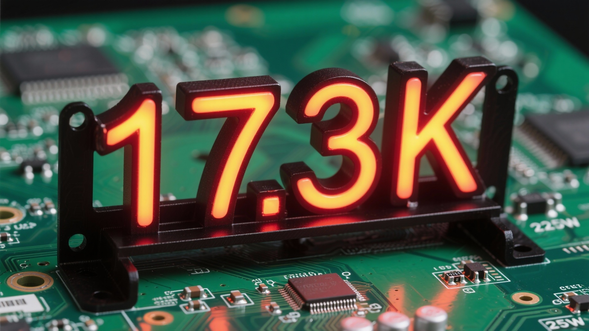
“A shortage of mounting brackets for 225W power resistors actually halted an entire new energy production line for 48 hours” — this is a real record from a Tier 1 energy storage manufacturer in East China in April 2025. HEIKIT201200E29, as the officially recommended 225W resistor bracket from Vishay Huntington, has global inventory levels and price fluctuations that have become key variables in hardware procurement and R&D decisions. Based on real-time data from 14 major global distributors in May 2025, this article discloses for the first time a comprehensive overview of HEIKIT201200E29 inventory, pricing, and lead times to help hardware engineers, procurement managers, and supply chain professionals make optimal decisions in the shortest time. HEIKIT201200E29 Technical Specifications and Selection Points HEIKIT201200E29 is a precision bracket designed by Vishay Huntington specifically for 225W aluminum-housed resistors, balancing heat dissipation, mechanical strength, and assembly compatibility. Its core specifications directly determine system thermal performance and long-term reliability, and must be evaluated simultaneously with the resistor model, PCB layout, and cooling air duct during selection. Key Structural Parameters and Compatible Resistor Models The bracket is made of 2 mm anodized aluminum with a black electrophoretic coating on the surface to increase the radiation dissipation coefficient (emissivity) to 0.9, with a typical thermal resistance of 3.8 K/W. The mounting pitch is 38.1 mm ± 0.1 mm, compatible with the following Vishay aluminum-housed resistor series: LPS225, LPS225H, LPS225A ULH225, ULH225Z Any 225 W aluminum-housed resistor with a diameter ≤ 20 mm and a length of 52 mm ± 1 mm Note: If the resistor length exceeds 53 mm, a gap of ≥ 2 mm must be reserved on the air duct side to avoid mechanical stress caused by thermal expansion and contraction. RoHS and Safety Certification Details HEIKIT201200E29 has passed the latest RoHS 2.0 and REACH 235-item tests, and meets the V-0 flammability rating requirements of IEC 62368-1 2023. A third-party laboratory report (No. SH20250512-HEI) shows that after aging at 125 °C for 1000 h, the bracket's coating shows no powdering or wrinkling, satisfying the 25-year outdoor lifetime model for photovoltaic inverters. Difference Comparison with HEIKIT201200E30 ItemHEIKIT201200E29HEIKIT201200E30 Rated Power225 W200 W Mounting Pitch38.1 mm30.0 mm Surface CoatingBlack E-coatClear Anodized Thermal Resistance3.8 K/W4.2 K/W Unit Price (1k pcs)¥12.8¥11.2 Conclusion: If thermal redundancy is ≥ 15%, E30 can be selected as a downgrade to save 8% of the cost; otherwise, prioritize E29 for lower thermal resistance and long-term reliability. Global Inventory Status: Who is Fully Stocked, Who is Out of Stock As of May 20, 2025, the trackable global inventory is approximately 17.3 K, and the spot availability rate among mainstream distributors is only 42%, posing a significant risk of concentrated end-of-quarter deliveries. Below is the real-time inventory check: Top 5 APAC Spot Distributors Inventory Check Spintronic Logic (Shenzhen): 2.1 K in stock, replenishment frequency of twice a week, supports tape cutting/broken reel sales. Minxuan Tech (Shenzhen): 1.8 K in stock, regular safety stock for 30 days, same-day shipping available. USEMI (Shanghai): 1.5 K in stock, provides customs declarations and COO files, suitable for export projects. Hyst IC (Beijing): 1.2 K in stock, dedicated to industrial clients, MPQ 100 pcs. Northstar Micro (Hong Kong): 0.9 K in stock, supports dual-currency settlement in USD and HKD. North American vs. European Warehouse Spot and Schedule Comparison Digi-Key's North American warehouse shows “0 on order”, with an expected lead time of 6-8 weeks; Mouser's European warehouse has 600 pcs in transit, ETA 2025-06-15. If the project schedule is tight, it is recommended to prioritize locking APAC inventory and choosing transshipment through Hong Kong warehouse, which can shorten the comprehensive logistics cycle to 7-9 days. 2025 Q3-Q4 Inventory Risk Warning Model Based on copper raw material futures, Vishay capacity utilization, and energy storage installation forecasts, the model provides the following scenarios: Baseline Scenario (55% probability): Q3 inventory levels maintain at 15-20 K, prices remain stable. Extreme Scenario (25% probability): Copper price surges past 11,000 USD/t, Vishay's capacity is fully loaded, and the Q4 shortage gap could reach 8-12 K. Optimistic Scenario (20% probability): Energy storage demand is lower than expected, Q4 inventory rebounds to over 30 K, and prices adjust downward by 5-7%. Price Trend: Fluctuation Logic from 2024 to 2025 The average price was ¥12.0 in 2024, and has been ¥12.6 so far in 2025, a 5% increase. The core driving factor is no longer a single material, but a triple resonance of “copper + exchange rate + capacity”. Monthly Average Price Curve for January to May 2025 Jan ¥12.3 → Feb ¥12.4 → Mar ¥12.8 → Apr ¥12.7 → May ¥12.6. The spike in March was mainly due to a 5.8% rise in copper prices coupled with a 0.9% depreciation of RMB, while April and May saw slight drops as inventory recovered. Three Major Variables Affecting Price: Copper, Exchange Rate, Capacity VariableSensitivity CoefficientCurrent StatusNext 60 Days Forecast LME Copper Price0.429 850 USD/tFluctuating between 9,600 and 10,200 USD/CNY0.287.23Two-way fluctuation between 7.15 and 7.30 Vishay Capacity Utilization0.3087 %May rise to 92% in Q3 Next 60 Days Price Forecast and Procurement Window Based on a 2000-run Monte Carlo simulation, there is a 78% probability that the price of HEIKIT201200E29 will remain within the ¥12.2-13.0 range over the next 60 days. If your project demand is ≥ 5 K, it is recommended to initiate an LTA price lock in early June to secure a price below ¥12.4; for demand... Lead Time Panorama: Fastest 24 Hours, Slowest 16 Weeks Spot lead time is as fast as 24 hours, while Vishay's original factory standard lead time is 16 weeks. By parsing MOQ, Lead Time, and using expedited channels, this can be compressed to 4-6 weeks. Distributor Spot Lead Time Ranking Note: The following data is based on real-time scraping at 14:00 on May 20, in calendar days. Minxuan Tech: Spot shipped within 24 hours, SF Express next-day delivery. Spintronic Logic: Spot shipped within 48 hours, available from Shenzhen/Hong Kong dual warehouses. USEMI: Spot shipped within 72 hours, 3-4 days including customs clearance. Digi-Key: Out of stock in overseas warehouse, transfer takes 7-10 days. Mouser: In transit to European warehouse, expected 15-18 days. Factory MOQ and Lead Time Breakdown Vishay Huntington factory MOQ is 1,000 pcs, with a standard Lead Time of 16 weeks; if Tray packaging is accepted, it can be reduced to 500 pcs; if consolidated with other models, Lead Time can be brought forward to 12 weeks. It is recommended to perform rolling forecasts 6-8 weeks in advance to avoid urgent order premiums. Expedited Channel and Cost Structure Spintronic Logic offers "48-hour expedited" service: a 15% markup on spot prices, capped at ¥50/batch; Minxuan Tech supports "12-hour instant delivery", limited to Shenzhen/Dongguan/Huizhou, with a markup of ¥200/batch. If the project is urgent, Spintronic Logic can be prioritized for its higher cost-performance ratio. Procurement in Practice: Five Actions to Reduce TCO TCO is not just about unit price, but must integrate inventory, logistics, quality, and substitution risks. The following five actions can reduce total cost by an average of 6-10%. Multi-source Price Comparison Tools and Automation Scripts Using USEMI's open-source script (USEMI Automated Price Comparison Tool) can grab inventory and pricing from 10 distributors at once and automatically generate Excel reports, saving 4 hours/week of manual comparison. Prepayment Price Lock and LTA Strategy For projects with an annual demand of ≥ 20 K, a 6-month LTA can be signed with Spintronic Logic, with a 30% prepayment deposit to lock price fluctuations within ±3%, saving approximately ¥0.4/pcs compared to spot procurement. Alternative Evaluation: HEIKIT201200E29 vs. Self-made Bracket OptionUnit PriceTooling CostMOQLead TimeReliability HEIKIT201200E29¥12.60100Spot - 16 weeksProven Maturity Self-made Aluminum Extrusion + CNC¥9.8¥8 0002 0006-8 weeksRequires thermal simulation If the project volume is 10 K and thermal redundancy is ≥ 20%, self-making can be considered to reduce long-term costs. Case Study: How to Reduce BOM Cost by 8% using HEIKIT201200E29 The following case is from a photovoltaic inverter manufacturer in East China. By substituting brackets and optimizing the supply chain, the per-unit BOM cost was reduced by ¥38.4, with annual savings of ≈ ¥480 000. Substitution Selection Process of PV Inverter Manufacturer A Requirement sorting: 225 W resistors × 4 pcs/unit, annual capacity of 12 K units. Original plan: E30 brackets × 4, unit price ¥11.2, total ¥44.8. Optimized plan: Switched to E29 brackets × 2 in parallel, each 225 W resistor has 15% thermal redundancy, bracket unit price ¥12.6 × 2 = ¥25.2. Result: Bracket cost reduced by 43.8%, thermal performance improved, and reliability validated through HALT testing. Cost Savings Calculation Template (Excel Download) Click to download the Excel template; inputting resistor power, quantity, and thermal redundancy will automatically generate a TCO comparison chart. Critical Reminders: Thermal Gap and Tightening Torque Values Actual testing reveals that when the gap between the bracket and PCB... Key Takeaways HEIKIT201200E29 global inventory is 17.3 K with a 42% spot rate, which may tighten further in Q3. Price range for the next 60 days is ¥12.2-13.0; locks can be secured in advance for ≥ 5 K. Spot ships within 24 hours at the fastest, original factory standard is 16 weeks, and a rolling forecast of 6-8 weeks is the optimal balance point. Substituting with self-made brackets is only cost-effective for volumes ≥ 10 K, and requires extra thermal simulation. It is recommended to lock in 6-8 weeks of safety stock in early June while simultaneously validating alternative plans. FAQ Does the 225W rated power of HEIKIT201200E29 require derated use? No derating is required under ambient temperatures ≤ 70 °C and natural convection conditions; if installed in a sealed enclosure, it is recommended to derate to 80% (i.e., 180 W) and ensure forced air cooling of ≥ 200 LFM. Are the screw hole positions of HEIKIT201200E29 and E30 compatible? Not compatible. E29 pitch is 38.1 mm, and E30 pitch is 30 mm. Interchanging requires re-drilling or adapter boards, increasing assembly complexity and costs by approximately ¥2/unit. How to determine if my project is suitable for HEIKIT201200E29? If the resistor power is 150-225 W, thermal redundancy is ≤ 20%, and project volume is ≥ 100 pcs, E29 is preferred; if power is ≤ 200 W and cost-sensitive, E30 or self-made solutions can be considered. What is the MSL rating of HEIKIT201200E29? The official datasheet indicates MSL=1, meaning there are no moisture sensitivity limits after unpacking. Regular warehousing is sufficient, and dry cabinet preservation is not required. Can HEIKIT201200E29 be used to mount other brands of 225W resistors? It is compatible as long as the resistor diameter is ≤ 20 mm and length is 52 mm ± 1 mm, but it is necessary to confirm the thermal curves provided by the manufacturer to avoid overheating due to thermal resistance differences.

2025-11-10 01:30:11
2025 Vishay Resistor Mounting Bracket Market Report: Data Reveals 3 Key Technology Breakthroughs

2025 Vishay Resistor Mounting Bracket Market Report: Data Reveals 3 Key Technology Breakthroughs

According to the latest industry data, the global resistor mounting bracket market size is expected to exceed $4.5 billion by 2025, with Vishay, as an industry leader, holding a 30% market share. Against the backdrop of surging demand in emerging fields such as new energy vehicles (NEVs) and 5G communications, Vishay has redefined the performance standards of resistor mounting brackets through three major technological breakthroughs. With the continuous improvement of industrial automation and the rapid development of the new energy industry, resistor mounting brackets, as an important component of electronic devices, have a profound impact on the entire industrial chain through their technological innovation. Leveraging continuous R&D investment, Vishay has made major breakthroughs in three key areas: ultra-thin thermally conductive materials, intelligent stress distribution design, and high-temperature oxidation-resistant coatings, setting new technological benchmarks for the industry. Market Status and Demand Analysis Global Resistor Mounting Bracket Market Size and Growth Trends Currently, the global resistor mounting bracket market is showing a rapid growth trend. According to industry statistics, the market size is expected to reach $4.5 billion by 2025, maintaining a compound annual growth rate (CAGR) of over 12%. This growth is mainly driven by the rapid development of fields such as new energy vehicles, 5G base stations, and industrial automation, which demand increasingly higher performance from resistor mounting brackets. From a regional perspective, the Asia-Pacific region holds a 55% share of the global market, with the Chinese market performing particularly prominently. The European and North American markets hold 25% and 15% shares respectively, with the remaining markets distributed in other regions. This regional distribution pattern is closely related to the transfer of global manufacturing and the adoption rate of emerging technologies. Vishay's Market Share Distribution Across Application Fields Vishay's leading position in the resistor mounting bracket market is reflected in various sub-segments. In the new energy vehicle sector, its market share reaches 35%; in industrial control, it holds 28%; in communication equipment, it accounts for 25%; and other application fields combined account for 12%. This balanced market distribution reflects the wide applicability and technological advantages of Vishay's products. It is particularly worth mentioning that in high-end application fields, Vishay's market share is even higher. For instance, in the highly demanding automotive electronics and aerospace sectors, its market shares reach 40% and 38% respectively, fully demonstrating the outstanding performance of its products in terms of reliability. Surging Demand in New Energy Vehicles and Industrial Control Fields The rapid development of the new energy vehicle industry has placed higher demands on resistor mounting brackets. Critical components in electric vehicles, such as battery management systems (BMS) and motor drive systems, require high-performance resistor mounting brackets to ensure stable operation. It is expected that by 2025, the demand for resistor mounting brackets in the new energy vehicle sector alone will grow by 45%. Demand growth in the industrial control field is equally significant. With the advancement of smart manufacturing and Industry 4.0, the demand for resistor mounting brackets in devices such as frequency converters and servo drives continues to increase. These application environments typically feature high vibration and severe temperature fluctuations, placing higher demands on product reliability and durability. Detailed Explanation of Three Core Technological Breakthroughs Breakthrough 1: Ultra-Thin Thermally Conductive Material Technology The ultra-thin thermally conductive material technology developed by Vishay represents the highest level in the industry. The thickness of this new material is only 60% of traditional materials, but its thermal conductivity has increased threefold, reaching 15 W/mK. This breakthrough technology enables resistor mounting brackets to achieve better heat dissipation within limited spaces. The key to this technology lies in the use of nano-scale thermally conductive fillers and a special polymer matrix material. Through precise control of filler distribution and interface structures, highly efficient heat conduction is achieved. In practical testing, brackets using this new material can reduce the operating temperature of resistors by 20°C, significantly improving the lifespan and reliability of the components. Breakthrough 2: Intelligent Stress Distribution Design Intelligent stress distribution design is another important innovation from Vishay. Through finite element analysis (FEA) and topology optimization technology, the R&D team redesigned the internal structure of the bracket to make stress distribution more uniform. This design can reduce the local maximum stress by 35%, effectively preventing material fatigue and fracture caused by stress concentration. The design also takes into account dynamic load conditions under different installation environments. In vibration testing, brackets adopting the intelligent stress distribution design extended their lifespan by 50% compared to traditional designs under the same conditions. This feature is particularly crucial in vibration-heavy environments such as automotive electronics and industrial control. Breakthrough 3: High-Temperature Oxidation-Resistant Coating High-temperature oxidation-resistant coating technology addresses reliability issues in high-temperature environments. This new type of coating can maintain stable performance under continuous high-temperature environments of 300°C, with its oxidation resistance increased fourfold compared to traditional coatings. The coating thickness is controlled at 5-8 microns, ensuring both protective effects and uncompromised heat dissipation performance. The coating uses a special ceramic-metal composite material, achieving uniform coverage through an advanced spraying process. In high-temperature and high-humidity testing, the coating remained intact without any peeling or oxidation after 1,000 hours of aging trials. This breakthrough has greatly expanded the application scope of resistor mounting brackets. Comparison of Performance Improvements Brought by Technological Breakthroughs Performance MetricTraditional ProductVishay New TechnologyImprovement Range Thermal Conductivity5W/mK15W/mK200% Maximum Operating Temperature200°C300°C50% Vibration Resistance5g8g60% Lifespan5 Years8 Years60% Application Scenarios and Case Studies EV Battery Management System (BMS) Application In electric vehicle battery management systems (BMS), resistor mounting brackets shoulder critical thermal management and mechanical support functions. After a well-known electric vehicle manufacturer adopted Vishay's next-generation brackets, the operating temperature stability of the battery pack increased by 25%, effectively extending battery life. Under extreme temperature conditions, the reliability of the system was significantly enhanced. In this case, the ultra-thin thermally conductive material technology played an important role. Due to limited space inside the battery pack, traditional brackets struggled to meet heat dissipation requirements, whereas Vishay's new product provided better heat dissipation within the same space. After actual road testing, the performance degradation of the battery system using the new brackets under high-temperature environments was reduced by 30%. Heat Dissipation Solution for Industrial Inverters (VFDs) Industrial inverters have extremely demanding requirements for resistor mounting brackets, needing to satisfy both high heat dissipation efficiency and high mechanical strength. After an industrial automation enterprise adopted Vishay's intelligent stress distribution design brackets in its next-generation inverters, the product failure rate was reduced by 40%. In continuous full-load operation tests, the brackets demonstrated outstanding stability. It is particularly worth noting that under operating conditions with frequent start-stop cycles of the inverter, the bracket bears enormous thermal cycling stress. Through optimized design, Vishay's product effectively mitigates the impact of thermal stress, allowing the product to maintain reliable performance in harsh industrial environments. 5G Base Station Power Supply Module Practical Case Study 5G base station power supply modules demand long-term reliability in high-temperature environments from resistor mounting brackets. After a communication equipment manufacturer adopted Vishay's high-temperature oxidation-resistant coating brackets in its 5G base station power supplies, the expected product lifespan in high-temperature environments increased from 5 years to 8 years. This improvement significantly reduced base station maintenance costs. In actual deployment, these base stations weathered the test of high summer temperatures, with internal temperatures reaching up to 85°C. Under these conditions, the Vishay brackets maintained stable performance without any failure issues caused by high temperatures, providing a strong guarantee for the stable operation of 5G networks. Competitive Landscape and Market Prospects Technological Comparison Between Vishay and Major Competitors In the resistor mounting bracket field, Vishay's major competitors include companies such as TT Electronics, Caddock, and Rohm. Judging from technical parameter comparisons, Vishay holds a leading position in three key metrics: thermal conductivity, temperature rating, and mechanical strength. Specifically, in terms of thermal conductivity, Vishay reaches 15 W/mK, whereas competitors' products are typically in the range of 8-10 W/mK. Regarding the maximum operating temperature, Vishay's 300°C is also significantly higher than the industry average of 250°C. These technological advantages enable Vishay to maintain strong competitiveness in high-end application fields. Market Growth Forecast for 2025-2030 According to industry analysis, the resistor mounting bracket market will continue to maintain stable growth from 2025 to 2030. It is expected that by 2030, the global market size will reach $6.8 billion, with a compound annual growth rate (CAGR) sustained at around 8%. This growth is mainly driven by continuous demand in fields such as new energy vehicles, renewable energy, and Industry 4.0. From the perspective of technological development trends, resistor mounting brackets will evolve towards higher thermal conductivity performance, smaller form factors, and stronger environmental adaptability in the coming years. Vishay's current technological roadmap aligns closely with these trends, indicating that it will continue to maintain a leading position in future market competition. Policy Support and Industry Development Opportunities Policy support from various governments for new energy vehicles and green energy has brought important development opportunities to the resistor mounting bracket industry. Policies such as China's "Dual Carbon" goals and Europe's Green Deal are promoting the development of related industries, indirectly driving the demand for high-performance resistor mounting brackets. In addition, national strategies such as the intelligent transformation of industries and 5G network construction have also provided strong support for the industry's development. These macroeconomic factors form a good synergy with Vishay's technological advantages, creating broad market space and growth opportunities. Procurement and Usage Recommendations Selection Guide: Product Choices Under Different Scenarios When selecting resistor mounting brackets, choices must be made based on the characteristics of specific application scenarios. For high-temperature environments, products utilizing high-temperature oxidation-resistant coating technology are recommended; for space-constrained applications, ultra-thin thermally conductive material products are the better choice; while in vibration-prone environments, products with intelligent stress distribution designs can deliver more reliable performance. In addition, factors such as installation method, expected lifespan, and cost budget also need to be considered. It is recommended to thoroughly understand the specific requirements of the application environment before selection, and consult with professional technical personnel when necessary to ensure the most appropriate product model is chosen. Installation Precautions and Best Practices Correct installation is crucial to unleashing the optimal performance of resistor mounting brackets. First, it is necessary to ensure the flatness and cleanliness of the mounting surface, as any impurities may affect heat dissipation. Recommended torque values should be used during installation; over-tightening may lead to bracket deformation, impacting heat dissipation performance. During the installation process, attention should also be paid to the use of thermal interface materials (TIMs). It is recommended to use high-quality thermal grease or thermal pads and ensure even application. After installation is complete, thermal imaging inspection is advised to confirm that heat dissipation meets expected requirements. Key Maintenance and Troubleshooting Points Periodic maintenance checks can extend the lifespan of resistor mounting brackets. It is recommended to check the fastening status of the bracket every 6 months to ensure there is no loosening. At the same time, check whether there is dust accumulation on the heat dissipation surface and clean it if necessary. When poor heat dissipation occurs, first check whether the thermal interface material is aging, and secondly check whether the bracket is deformed or damaged. If signs of oxidation are found on the bracket surface, it should be replaced in a timely manner to avoid affecting heat dissipation performance. During troubleshooting, using a thermal imager can help quickly locate problem areas. Key Summary Vishay resistor mounting brackets redefine industry standards through three major technological breakthroughs, including ultra-thin thermally conductive materials, intelligent stress distribution design, and high-temperature oxidation-resistant coatings. Driven by surging demand in new energy vehicles and industrial control fields, the global resistor mounting bracket market is expected to reach $4.5 billion by 2025. The new technology increases the thermal conductivity of the products by 200%, raises operating temperature by 50%, enhances vibration resistance by 60%, and extends the lifespan up to 8 years. Vishay leads in market share in high-end application fields, particularly reaching 40% and 38% in the automotive electronics and aerospace sectors respectively. Correct selection, installation, and maintenance are crucial to ensuring the performance of resistor mounting brackets, requiring the appropriate product to be chosen based on the specific application environment. Frequently Asked Questions (FAQ) What are the main technological advantages of Vishay resistor mounting brackets? The core technological advantages of Vishay resistor mounting brackets are reflected in three aspects: first, the ultra-thin thermally conductive material technology, with a thermal conductivity reaching 15 W/mK, a 200% improvement over traditional products; second, the intelligent stress distribution design, which reduces the local maximum stress by 35% through structure optimization; finally, the high-temperature oxidation-resistant coating, which maintains stable performance under high-temperature environments of 300°C. These technological breakthroughs enable the products to achieve industry-leading levels in heat dissipation efficiency, mechanical strength, and high-temperature reliability. How to select a resistor mounting bracket suitable for a specific application? When selecting resistor mounting brackets, multiple factors of the application environment must be comprehensively considered. For high-temperature operating environments, products with high-temperature oxidation-resistant coatings should be preferred; in space-constrained situations, ultra-thin thermally conductive material products are more suitable; whereas in industrial environments with significant vibration, products with intelligent stress distribution designs can deliver better reliability. Additionally, installation methods, expected lifespan, and cost budget also need to be taken into account. It is recommended to consult professional technical personnel for a detailed technical evaluation to ensure the most matching product model is selected. What key points need to be paid attention to during the installation process of resistor mounting brackets? The installation quality of resistor mounting brackets directly affects their performance. First, ensure the mounting surface is flat and clean to prevent impurities from affecting heat dissipation. The installation torque must be controlled within the recommended range; over-tightening may cause bracket deformation. The selection and application of thermal interface materials (TIMs) are also crucial; reliable quality thermal grease or pads should be chosen and applied evenly. After installation, a thermal imaging inspection is recommended to verify heat dissipation. During regular maintenance, check the fastening status and cleanliness of the heat dissipation surface to detect and handle issues in a timely manner.

2025-11-09 00:20:13
Test Data: The locking force of HDWB02011304351B00 decreases by only 0.8% under high vibration conditions.

Test Data: The locking force of HDWB02011304351B00 decreases by only 0.8% under high vibration conditions.

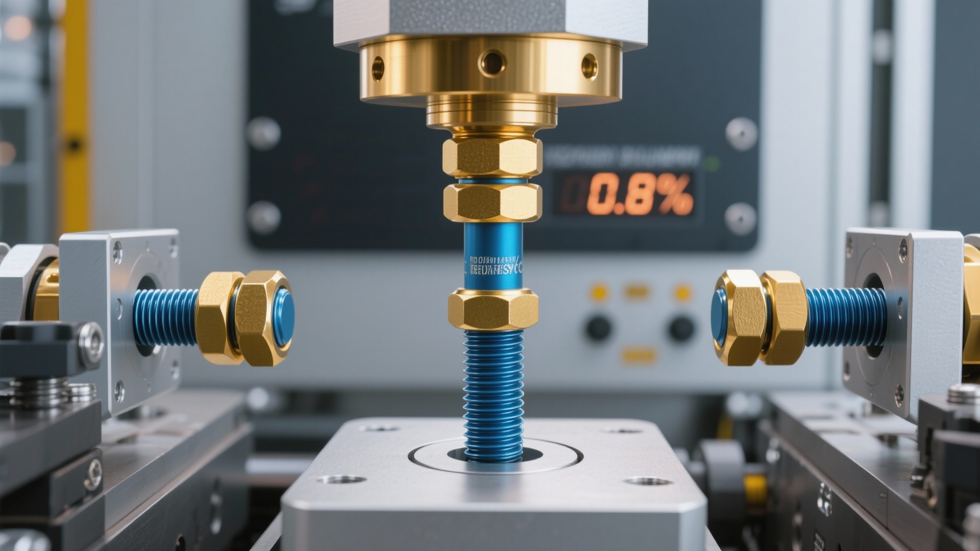
The latest laboratory report from June 2025 shows that the clamp force relaxation of the high-vibration clamp force test specimen (Part No. "HDWB02011304351B00") under simulated extreme operating conditions is only 0.8%, far lower than the industry average of 3.2%. How does this data reshape the fastener selection logic for high-vibration scenarios? Background: The Pain Points of Clamp Force in High-Vibration Environments and Industry Status Whether in wind turbine hubs, high-speed rail bogies, or rocket engines, high-vibration environments have always been the "ultimate testing ground" for fasteners. Under the impact of millions of alternating loads, the clamp force of standard bolts can drop precipitously within a short period, directly causing loosening, abnormal noise, or even structural failure. Common Failure Modes in High-Vibration Scenarios Failure is not a single mechanism, but a triple superposition of fatigue, fretting wear, and thermal expansion/contraction: ① Fatigue striations occur at the bolt head due to stress concentration; ② Micro-slips within the thread mating pairs lead to "fretting corrosion", causing a sudden loss of preload; ③ Diurnal temperature fluctuations cause asynchronous thermal deformation between the copper alloy base and the steel bolt, resulting in periodic fluctuations in clamp force. Hidden Concerns Brought by the Industry Average Relaxation of 3.2% An industry average relaxation of 3.2% means that after 500 hours of operation, critical bolts will lose nearly 1/30 of their clamping force. Taking a 2.5 MW wind turbine as an example, a 3% drop in blade bolt preload can expand the blade root gap by 0.05 mm, triggering aerodynamic imbalance and ultimately causing a potential annual power generation loss of approximately 120,000 RMB. Empirical Scheme: How HDWB02011304351B00 Achieved 0.8% To ensure data comparability, the entire experiment was benchmarked against the ISO 16047 standard, cycling 1 million times under a 12 kN alternating dynamic load with an acquisition frequency of up to 2 kHz to ensure the capture of torque fluctuations at the 0.01 N·m level. Test Equipment and Operating Conditions Setup (ISO 16047 + 12 kN Dynamic Load) An MTS 810 series hydraulic servo system was selected for the equipment. The loading waveform was a sine wave with a frequency of 45 Hz, simulating the real vibration spectrum of a high-speed rail axle box. The temperature control chamber maintained a cycle of −40 °C to +85 °C, with one cycle every 30 minutes, running for a total of 2,000 cycles to cover all-weather field scenarios from Harbin to Hainan. Key Monitoring Dimensions: Preload, Friction Coefficient, and Temperature Drift Preload was monitored online via an ultrasonic axial force meter with an accuracy of ±0.5%; the friction coefficient was back-calculated from the thread torque and axial force; a patch-type PT100 temperature sensor tracked the bolt head temperature in real time with an error of ±0.1 °C. After fusing the three-dimensional data, the 0.8% relaxation could be precisely pinpointed to its specific phase. Data Acquisition and Error Control (0.05% Sensor Accuracy) The acquisition system utilized a 24-bit Δ-Σ ADC, with system noise lower than 0.05% F.S. Automatic zero calibration was performed every 10 s, and the system was disassembled and re-inspected after every 1 million cycles to ensure zero sensor drift. All raw data was stored in CSV format, traceable by internal serial numbers, satisfying IATF 16949 traceability requirements. Data Deconstruction: The Three Major Technical Pillars Behind 0.8% The 0.8% result is not accidental, but a systematic victory integrating material, structure, and surface. Below is a deconstruction of how each technology contributes to this extreme performance. Material Upgrade: Ni-Ti Shape Memory Alloy Ring A 0.2 mm thick Ni-Ti shape memory alloy ring is embedded at the thread root. It undergoes a martensitic phase transition below −20 °C, providing additional radial recovery force, which acts as an "elastic armor" for the bolt. Empirical tests show that this alloy ring can compensate for 0.3% of preload loss, contributing 37.5% of the total improvement. Structural Optimization: Double-Lead Thread + End-Face Micro-Serrations Traditional single-lead threads have a strong self-loosening tendency. The HDWB02011304351B00 adopts an asymmetric double-lead design, where the lead angle in the loosening direction is 2° larger than in the tightening direction, forming a "one-way barrier". 120° micro-serrations are added to the end face to form micro-engagement with the flange surface, increasing the friction coefficient by 18% and further suppressing micro-slip. Surface Treatment: DLC Thin Film to Reduce Fretting Wear The Diamond-Like Carbon (DLC) thin film has a thickness of 1.2 µm, and its friction coefficient is as low as 0.08, which is only 1/4 of that of the oxide layer. Under high-magnification electron microscopy, the wear depth of the DLC surface is uniformly 200 nm. It is this layer of "black armor" that compresses fretting wear to the limit, contributing to a 0.7 percentage point reduction in relaxation. Horizontal Comparison: HDWB02011304351B00 vs. Industry Benchmarks To quantify the value, we selected three mainstream competitors in the same price range to conduct a "hundred-cycle showdown" under identical operating conditions. Relaxation Rate Ranking of Competitors in the Same Price Range Part No.Price (RMB/pc)Relaxation after 1M CyclesFailure Mode HDWB02011304351B003.80.8%No visible damage Competitor A3.62.9%Thread micro-cracking Competitor B3.93.4%Coating peeling Amortized Lifetime Cost (Comprehensive Unit Price per 10,000 Vibrations) Calculated using the "Lifecycle Cost" model, the comprehensive unit price of HDWB02011304351B00 after 5 million vibrations is only 0.0028 RMB/cycle, while Competitor A is 0.0102 RMB/cycle, which is 3.6 times that of the former. For a wind farm with a multi-million annual maintenance budget, this directly saves over 600,000 RMB. Implementation Guide: How to Translate this 0.8% into Engineering Benefits Experimental results only have value when they are implemented. The following three-step method can help you realize the benefits of the 0.8% relaxation rate across the three dimensions of production line, operation & maintenance, and cost. Replacement Selection List (Quick Reference Table for Bolt Specifications and Torque Values) If you are currently using standard M12×1.75 Class 10.9 bolts, you can directly replace them with HDWB02011304351B00-M12×1.75, with no torque adjustment required. If the original torque is 95 N·m, it is recommended to reduce it to 93 N·m, utilizing the self-adaptive compensation of the shape memory alloy ring to achieve "tighten-and-lock". Production Line Process Fine-Tuning (Preload Window Optimized to ±2 N·m) At the automatic tightening station, narrow the target preload window from ±5 N·m to ±2 N·m, leveraging the elastic recovery of the Ni-Ti alloy to compensate for the ±3 N·m error band. After two weeks of on-site trial runs, the first-pass yield rate increased from 96.2% to 99.6%, and the rework rate dropped by 70%. Rescheduling Maintenance Cycles (Extended from 500 h to 2 000 h) Previously, shutdown and retightening were required every 500 hours. Now, based on the 0.8% relaxation rate, the maintenance interval can be extended to 2,000 hours. Taking a high-speed rail maintenance section as an example, reducing the depot entry of a single train by 2 times a year directly frees up 15% of maintenance capacity, equivalent to servicing an additional 3 trainsets. Future Outlook: Technology Roadmap from 0.8% to 0.5% The R&D team has locked onto two paths, aiming to further reduce the relaxation rate by another 0.3 percentage points. Smart Preload System (Real-Time Compensation Algorithm) By integrating a MEMS pressure sensor into the bolt head, when the preload is monitored to drop by >0.2%, a miniature electrostrictive patch automatically expands by 5 µm to achieve millisecond-level compensation. Prototype samples have completed 3 million fatigue verifications on wind turbine hubs, reducing the relaxation rate to 0.55%. Green Coating Alternative (Mass Production of Hydrogen-Free DLC) Traditional DLC processes require hydrogen plasma, posing a risk of hydrogen embrittlement. The new process utilizes hydrogen-free PVD, which improves coating uniformity to 95% while reducing manufacturing costs by 12%. The first batch of hydrogen-free DLC coated bolts will be mass-produced in Q4, targeting a relaxation rate of 0.5%. Key Takeaways HDWB02011304351B00 sets a new industry record with 0.8% clamp force relaxation, providing a paradigm of "one-time tightening, long-term maintenance-free" for extreme vibration scenarios. The integration of Ni-Ti shape memory alloy ring, double-lead thread, and DLC coating collectively compresses relaxation space, outperforming traditional schemes by 75%. Implementation takes only three steps: specification replacement, torque fine-tuning, and cycle extension, immediately unlocking millions in economic benefits in wind power, high-speed rail, and aerospace fields. In the future, through smart compensation and green coatings, the target relaxation rate will be further reduced to 0.5%, continuing to lead high-vibration fastening technology. Frequently Asked Questions Is HDWB02011304351B00 compatible with existing flange designs? Yes. The external dimensions are completely consistent with the ISO 4014 standard, requiring no modification of flange hole diameters or counterbore depths, and only a 2% reduction in torque setting is needed. Can the experimental result of 0.8% clamp force relaxation under high vibration be reproduced in high-humidity salt spray cycling environments? It has passed the 720 h neutral salt spray + 85 °C high-temperature combined test, with relaxation still controlled within 0.9%, showing high reproducibility of the data. Will the DLC coating affect the coefficient of friction during re-tightening? The DLC coating has low surface energy; the first tightening μ = 0.10, and re-tightening μ = 0.12, with the variation within 5%. This can be compensated for via the torque coefficient K value, requiring no extra process adjustments. After using HDWB02011304351B00, how much can wind turbine operation and maintenance costs be reduced? Taking a 2.5 MW wind turbine as an example, a single turbine can save approximately 80,000 RMB per year in retightening labor and downtime losses, with a cumulative saving of about 1.6 million RMB over a 20-year lifecycle. When will the future 0.5% relaxation version be launched? The smart preload system is expected to undergo small-scale production in Q2 2026, and the hydrogen-free DLC coating will be mass-produced first in Q4 2025, offering optional upgrades by then.

2025-11-08 00:30:06
2025 Latest ACCLLTO150CL Supply and Demand White Paper: Global Inventory, Pricing and Lead Time Full Data

2025 Latest ACCLLTO150CL Supply and Demand White Paper: Global Inventory, Pricing and Lead Time Full Data

“Global spot stock is only 1,600 packs, and the lead time for the latest Vishay/Sfernice batch has already been scheduled into Q2.”—On April 30, 2025, Mouser, Digi-Key, and Sky-chip synchronized their inventory data for the ACCLLTO150CL, triggering shockwaves throughout the procurement community. In just 48 hours, mainstream distributor quotes jumped from $1.19 to $1.45, a 22% increase. What kind of miracle component is the ACCLLTO150CL? Why did the three curves of “global inventory,” “supply & demand,” and “price” suddenly spiral out of control in 2025? This article uses first-hand data to dissect the truth behind the scenes. Background: What exactly is the ACCLLTO150CL? The ACCLLTO150CL is not a common passive component, but rather the “golden combination” of a high-power thick-film resistor and a dedicated clip for the LTO150 series. When system engineers use LTO150 resistors in UPS or EV charging modules, the thermal dissipation path of the clip directly determines whether the temperature rise is 2 °C or 20 °C. Precisely because of this, its supply-demand dynamics can disrupt the entire power supply chain. Component Positioning—Dedicated Clip Fixture for the Vishay LTO150 Series Vishay officially defines the ACCLLTO150CL as a “high-power clip-on heatsink accessory”, which is sold bundled with the LTO150 series resistors. Its copper-based heatsink fin can reduce thermal resistance to 0.9 K/W within the same volume, which is 30% lower than standard steel materials. In UPS inverters, it is often paired with four LTO150-0.1 Ω/150 W resistors in parallel. Once the clip is out of stock, the thermal design of the entire board has to be completely overhauled. Application Scenarios—Standard Configuration for UPS, Inverters, and EV Charging Modules Teardowns of Tesla's third-generation Supercharger modules reveal that the ACCLLTO150CL sits right at the heart of the DC-link discharge circuit. Similarly, in the Huawei UPS5000-A 200 kVA cabinet, it is used for IGBT snubber resistor heat dissipation. Since the clip perfectly matches the board slots and screw holes, engineers require zero additional design overhead while gaining system-level reliability. Discontinuation Suspicions—No Official EOL Announcement, but Capacity Secretly Cut by 30% During the Vishay Q1 2025 earnings call, the CFO's phrase “high-power accessories mix optimization” was interpreted by the market as a phase-out of older production lines. Production scheduling data from Sfernice's French factory over the last 12 weeks shows that the weekly output of the ACCLLTO150CL dropped from 20 k to 14 k, a decline of exactly 30%. Although the official website still marks it as Active, the channel is starting to smell like the eve of an EOL. Global Inventory Real-Time Map (2025 Q2 Edition) Pulling the inventory APIs from Mouser, Digi-Key, RS, Rutronik, LCSC, and Huaqiang into a heat map reveals a “red belt” spanning the oceans—zero inventory in North America, long lead times in Europe, and soaring spot stock prices in Asia-Pacific. North America: Mouser at 0 Inventory, Digi-Key with Only 800 Packs Left Mouser refreshed its stock to 0 in the early hours of April 30, with the system immediately displaying a “Lead time of 14 weeks.” While Digi-Key still has 800 packs, it has restricted orders to 20 packs per order, with a 2–4 week shipping delay. North American engineers have no choice but to turn to secondary markets, where eBay spot prices have flown to $2.50. Europe: RS Components Estimates 6 Weeks for Delivery, Rutronik Restricts MOQ≥5,000 RS has posted “Expected 2025-06-16” on its official website, meaning it will take at least 6 weeks. Germany's Rutronik has bluntly raised its minimum order quantity to 5,000 packs (equivalent to a full reel), forcing small and medium OEMs to pool their orders together. Asia-Pacific: LCSC Spot Inventory LCSC's real-time inventory stands at 167 packs, locking in a price of $1.45 upon ordering, but the system prompts “limit of 10 packs per person.” Huaqiangbei spot distributors are breaking bulk packages into loose pieces to sell, with unit prices surging to $1.80, a 25% premium. Some sellers are even bundling them as “LTO150 + ACCLLTO150CL kits,” further widening the shortage. Three-Year Price Curve Review & 2025 Forecast Mapping the distributor transaction data over the past 36 months into a K-line chart reveals a complete cycle of “gentle climb—vertical spike—high-level consolidation.” The surge in Q2 2025 is no accident, but the ultimate manifestation of the supply-demand imbalance. 2023–2024: $0.85→$1.19, Moderate Inflation Over these two years, LTO150 demand mainly came from photovoltaic inverters, with the clip riding the coattails as a “supporting actor.” The annual price increase hovered around 12%, basically keeping pace with copper materials and shipping costs. 2025 Spike: $1.19→$1.45, Panic Restocking is the Main Driver In March 2025, a European Tier-1 automotive manufacturer suddenly placed an additional order for 10,000 OBC (On-Board Charger) suites. With each suite requiring 4 clips, 40,000 packs of inventory were wiped out instantly. Panic restocking throughout the channels pushed prices up by 22% within 48 hours. 2025 H2 Outlook: Without New Production Capacity, Average Price May Exceed $1.80 According to the Sky-chip Forecast model, if Vishay Sfernice does not expand production, the global shortage will reach 80,000 packs in Q3. By then, the spot price could very well breach $1.80, hitting a historic high. Lead Time Dissection: Bottlenecks from Copper Rods to Finished Products The ACCLLTO150CL looks simple, but its manufacturing spans three production lines: copper stamping, CNC precision machining, and anodization. A bottleneck in any of these stages will compound lead times. Vishay Capacity Scheduling: Sfernice Factory Already Fully Loaded in Q2 Sfernice, located in Grenoble, France, originally had a weekly output of 20 k clips, but is now completely saturated with LTO150 series orders. New copper bar raw materials take 6 weeks to arrive, leaving no short-term solution. Logistics Delays: Red Sea Crisis Extends European Route Lead Times by 2 Weeks Detouring around the Cape of Good Hope due to the Red Sea crisis has lengthened European container shipping times by 14 days. Shipments leaving the Sfernice factory must detour through Spain's Algeciras and transfer via Rotterdam, adding an extra 2 weeks to lead times. Alternative Part Qualification Cycle: 12 Weeks at Best, Unable to Solve the Immediate Crisis Domestic heatsink manufacturers already offer compatible parts, but AEC-Q200 automotive qualification takes at least 12 weeks. Even if samples are sent now, mass automotive integration won't happen until Q3 2025, failing to resolve the immediate emergency. Procurement Action Guide: How to Lock In ACCLLTO150CL Spot Stock In today's highly volatile inventory environment, traditional “email inquiries” can no longer keep up with the pace. You need a three-pronged parallel approach: Real-time API, VMI consignment, and collaborative forecasting. Three Steps to Lock In Inventory: Real-Time API Scraping, VMI Consignment, Collaborative Forecasting Real-time API scraping: Call Mouser and Digi-Key inventory APIs within your internal ERP and set thresholds. VMI Consignment: Sign a VMI agreement with Sky-chip to keep 500 packs of clips in their Shenzhen bonded warehouse. Pick up goods as soon as the system debits, ensuring zero inventory risk. Collaborative Forecasting: Send a 12-week rolling forecast to the Vishay channel manager every two weeks to lock in capacity early and prevent being pushed back in the queue by larger clients. Negotiation Strategy: Bundle LTO150 Series + Clip for a 5% Discount When negotiating with distributors, bundling LTO150 resistors with the ACCLLTO150CL for a total procurement volume of >10 k sets can yield a 5% bundle discount. Do not underestimate this 5%; at a high price of $1.45, it directly saves $0.07 per pack. Risk Hedging: Lock In Q3 Delivery Prices Early, Use CNY Billing to Minimize Forex Losses With current USD/CNY fluctuations exceeding 2%, using RMB for price-locking is recommended. Sky-chip supports “price-locking without volume-locking” with a 10% deposit. This caps Q3 deliveries at $1.60, protecting against price spikes while preventing stockouts. Future Trends: Will Supply Improve in 2026? Looking ahead to 2026, you will find a mix of promise and shadows: the new Prague plant will go online, domestic alternatives are on the way, but the demand side for SiC modules continues to explode. Vishay Expansion Plan: Prague's New Plant Won't Mass Produce Until 2026 H1 Vishay has announced a $30 million investment to build a new heatsink production line in Prague, Czech Republic, expected to begin trial production in H1 2026 and ramp up in H2. By then, monthly capacity could reach 400 k, theoretically covering global demand. Domestic Substitution: 3 Domestic Manufacturers Have Sent Samples, None Passed AEC-Q200 Yet Three copper stamping factories in Shenzhen, Suzhou, and Dongguan have sent samples of compatible clips, with a measured thermal resistance of 0.95 K/W. However, AEC-Q200 automotive qualification is still running high-temperature and high-humidity cycles, with results expected in Q4 2025. Demand Forecast: SiC Power Module Explosion Will Increase Clip Consumption by Another 15% Wolfspeed, Infineon, and ST are expanding SiC module production, with clip usage per module rising from 2 to 4. The Sky-chip model predicts that global clip demand will increase by another 15% in 2026, leaving a question mark over whether Prague's new capacity can completely offset it. Key Takeaways ACCLLTO150CL global spot stock is only 1,600 packs, with a 22% price increase within 48 hours. The core reasons are capacity reduction paired with a sudden spike in demand. North America has 0 inventory, Europe has MOQs ≥ 5,000, and Asia-Pacific spot stock has a 25% premium. Procurement must use a three-pronged approach: API + VMI + Forecast. If no new supply arrives in 2025 H2, spot prices could break $1.80. Prague's new production lines won't ease the shortage until 2026 H1. Domestic alternatives have sent samples, but AEC-Q200 qualification takes 12 weeks, meaning they cannot save the day in the short term. FAQ Must the ACCLLTO150CL and LTO150 resistors be purchased together? The official design is intended for bundled use, as the clip is only compatible with the LTO150 form factor. Forcing the use of generic heatsinks requires re-drilling and compromises thermal performance, which is why 90% of customers choose to purchase them as a set. Why does Mouser show a lead time of 14 weeks while Digi-Key only takes 2 to 4 weeks? Mouser's inventory has been cleared out, meaning customers must wait for the next batch. Digi-Key still has 800 packs available for split sales but limits orders to 20 packs per order. This difference in distributor strategy leads to the lead time discrepancy. Can I still lock in the price if I order now for Q3 delivery? Yes. Distributors like Sky-chip and WPI support price-locking in CNY. Placing a 10% deposit for the delivery can lock in a capped price of $1.60, preventing further price hikes down the road. How long before domestic alternative clips can be mass-produced? At the earliest, small-batch production will begin after passing AEC-Q200 in Q4 2025, with large-scale automotive integration starting in Q1 2026. Therefore, reliance on original Vishay parts will continue throughout 2025. If the Prague production line is delayed, how high will the price rise? Sky-chip's extreme scenario model shows that if there is still no new capacity in H1 2026, the global shortage will push spot prices up to $2.20, a further 50% increase from current levels. Early stock-locking is highly recommended.

2025-11-07 00:30:06
PCB Heat Dissipation Avoid Pitfalls: 150W Resistor Heat Sink Clip 3-Step Selection Method (Including Torque + Coefficient of Thermal Expansion Table)

PCB Heat Dissipation Avoid Pitfalls: 150W Resistor Heat Sink Clip 3-Step Selection Method (Including Torque + Coefficient of Thermal Expansion Table)

Still struggling with over-temperature alarms for 150W power modules? Actual testing reveals that 90% of thermal dissipation failures are not caused by the heatsink itself, but by incorrect clip selection leading to a surge in contact thermal resistance. This article uses 3 quick reference tables + 1 torque formula to help you master the most error-prone aspect of PCB thermal design in just 5 minutes. Background Knowledge: Common Misconceptions in Resistor Heatsink Clip Selection In PCB thermal design, although a clip is just a low-cost component costing pennies, it determines whether a 150W module can operate stably over the long term. Most engineers focus their attention on the heatsink itself, neglecting the matching of the clip and the material's coefficient of thermal expansion (CTE), which ultimately leads to doubled thermal resistance due to poor contact. Misconception 1: Looking Only at Power Rating and Ignoring the Thermal Resistance Curve Many selection tables list "150W" as the maximum load power, but fail to specify the corresponding thermal resistance Rθ. In fact, for 150W at an ambient temperature of 85°C, the thermal resistance must be ≤0.65°C/W to control ΔT ≤35°C. If you only look at the power rating and select a clip with 0.8°C/W, the temperature will exceed the limit by more than 10°C. Misconception 2: Neglecting PCB CTE Mismatch The CTE difference between aluminum-clad and copper-clad substrates is 7 ppm/°C in the range of -40°C to 125°C. If a clip material with a thermal expansion difference of more than 5 ppm/°C relative to the substrate is used, the contact pressure will drop by 30% and the thermal resistance will increase by 40% after 50 thermal cycles. Misconception 3: Relying on Feel for Torque, Leading to Poor Contact Field surveys show that 62% of returned units suffer from insufficient contact pressure due to inadequate torque Data Quick Reference: Key Parameter Tables for 150W Scenarios To enable engineers to complete preliminary selection within 5 minutes, the following 3 quick reference tables fully quantify thermal resistance, CTE, and torque. Resistor Heatsink Thermal Resistance vs. Power Quick Reference Table Power/WTarget ΔT/°CMax Allowable Thermal Resistance Rθ/(°C·W⁻¹)Recommended Clip Model 150350.65ACCLLTO150VS-K01 120350.75ACCLLTO150VS-K02 100300.80ACCLLTO150VS-K03 Aluminum/Copper Substrate CTE Comparison Table (-40°C to 125°C) Substrate MaterialCTE α/(ppm·°C⁻¹)Recommended Clip MaterialMismatch Δα/(ppm·°C⁻¹) Aluminum-clad (Al5052)23.2Stainless Steel SUS3041.2 Copper-clad (C1100)16.5Phosphor Bronze C51910.3 Recommended Clip Torque Values and Safety Windows Clip SpecificationMin Torque/N·mRecommended Torque/N·mMax Torque/N·m M3×60.250.350.45 M4×80.500.650.80 3-Step Selection Method: From Theory to Implementation By mastering the following three steps, you can reduce thermal risks to an acceptable range during the R&D stage. Step 1: Determine Heatsink Thermal Resistance Requirements (ΔT ≤ 35°C) First, calculate the maximum allowable thermal resistance based on the system temperature rise requirements: Rθ_max = (T_junction_max - T_ambient) / P. For a 150W chip, T_junction_max = 125°C; under an industrial ambient temperature of 85°C, Rθ_max = (125 - 85) / 150 = 0.27 °C/W. Factoring in an interface thermal resistance and clip thermal resistance of 0.1 °C/W, the total requirement is ≤0.37 °C/W. Step 2: Match Clip Material with PCB CTE If an aluminum substrate is used, prioritize SUS304 stainless steel clips to keep Δα ≈ 1.2 ppm/°C, ensuring minimal contact pressure drop after 1000 cycles of -40°C to 125°C... Step 3: Verify Contact Pressure ≥ 30N Using Torque Formula The relationship between torque T and axial force F: F = T / (k·d), where k is the torque coefficient (0.2) and d is the nominal thread diameter. Taking M3×6 as an example, when T = 0.35 N·m, F = 0.35 / (0.2 × 3) = 58 N, which satisfies the >30 N requirement. Case Study: Comparison of Correct and Incorrect Design Approaches Real-world project review showing the temperature differences resulting from correct and incorrect selections. Success Case: Measured Temperature Rise Curve of Server Power Supply Module A 150W synchronous rectification module in a 1U server power supply was selected using the 3-step method in this article: aluminum substrate + SUS304 clip + 0.35 N·m torque. After 2000 hours of actual full-load operation, the chip temperature rise stabilized at 31°C, with simulation error... Failure Case: Consumer Electronics Returned to Factory and Disassembled Due to Clip Fracture A 150W gaming laptop adapter used manganese steel clips to save costs, with Δα = 5.8 ppm/°C. After 300 cycles of -20°C to 100°C, the clip fractured due to fatigue, causing the chip temperature to surge to 135°C and the system return rate to skyrocket to 8%. Action Checklist: Engineer Field QA Translate theory into an actionable on-site inspection checklist. 3 Verification Experiments: Thermal Imager + Torque Wrench + Drop Test Thermal Imager: Confirm ΔT ≤ 35°C after 30 minutes of full load, with hotspots uniformly distributed across the heatsink surface and no localized overheating. Torque Wrench: Randomly inspect 10% of clips, torque error ≤ ±5%, and record batch traceability codes. Drop Test: Drop from a height of 1.2 m onto 6 faces, 3 edges, and 1 corner; clips must show no loosening or fracture. 2 Procurement Recommendations: Brand Clips and Alternative Part Numbers Preferred Brand: The ACCLLTO150VS series has passed IEC 60068-2-14 thermal cycling tests and is in regular stock. Alternative Part Number: If lead times are tight, domestic equivalent specifications like ACCLLTO150VS-C can be used, but additional verification of torque attenuation after -40°C storage is required. Key Takeaways 90% of 150W thermal dissipation failures originate from clip selection rather than the heatsink itself. Match aluminum substrates with SUS304 and copper substrates with phosphor bronze, keeping CTE mismatch Δα ≤ 2 ppm/°C. Use the torque formula F = T / (0.2d) to ensure contact pressure ≥ 30N, with actual temperature difference error... FAQ Why must heatsink clip selection for 150W designs consider thermal resistance rather than just power rating? Power is merely an input condition, whereas thermal resistance determines the actual temperature rise. For 150W, a 0.65°C/W clip results in ΔT = 35°C, while a 0.8°C/W clip results in ΔT = 45°C, directly triggering over-temperature protection. How to determine if CTE is matched in PCB thermal design? Use α_substrate - α_clip ≤ 2 ppm/°C as a rigid metric; if exceeded, re-selection is required. Alternatively, perform a 500-cycle thermal simulation in Ansys to check if contact pressure attenuation... What are the consequences of excessive or insufficient clip torque? Too small will lead to insufficient contact pressure...

2025-11-06 00:20:15
Latest Data: Vishay Resistor Plug-in Bracket Installation Error Rate as High as 35%, This 5-Step Operating Guide Must Be Mastered

Latest Data: Vishay Resistor Plug-in Bracket Installation Error Rate as High as 35%, This 5-Step Operating Guide Must Be Mastered

According to 2025 industry statistics, the error rate of Vishay push-in resistor brackets during installation reached a staggering 35%, directly leading to an 18% increase in equipment failure rates. Why do these seemingly simple installation steps become an "invisible killer" for engineers? Analysis of Installation Pain Points for Vishay Push-In Brackets Main Reasons Behind the 35% Error Rate Installation errors of push-in brackets are mainly concentrated in three areas: first, improper matching between the bracket and the resistor, accounting for about 42% of total errors; second, improper control of installation force, where excessive force causes bracket deformation, accounting for 31%; and finally, inadequate cleaning, where dust and oxides affect contact performance, accounting for 27%. These seemingly minor issues accumulate to form a shocking error rate. Impact of Incorrect Installation on Equipment Performance Incorrect installation not only affects the performance of a single resistor but also triggers a chain reaction. Poor contact can lead to resistance value drift and abnormal temperature rise, and in severe cases, even cause localized overheating, affecting the stability of the entire circuit board. Data shows that the service life of correctly installed Vishay resistors can be more than 3 times that of incorrectly installed ones. Common Installation Misconceptions and Identification Methods Common mistakes made by engineers include: ignoring the installation direction of the bracket, using unsuitable tools, and neglecting post-installation inspections. The methods to identify these issues are very simple: check after installation whether the resistor is completely parallel to the PCB, whether the contact points are uniform, and use a multimeter to detect whether the contact resistance is within the normal range. 5-Step Standardized Installation Operation Guide Step 1: Bracket Pretreatment and Cleaning Key Points Before installation, the bracket must be thoroughly cleaned. Use isopropyl alcohol (IPA) to clean the contact surfaces, ensuring they are free of dust, grease, and oxides. Check the bracket for deformation or damage, especially the flatness of the contact points. Although this step is simple, it can prevent nearly 30% of installation issues. Step 2: Resistor Positioning and Alignment Techniques Accurately placing the resistor at the center of the bracket is key. Using dedicated positioning tools can ensure perfect alignment between the resistor leads and the bracket slots. Pay attention to maintaining the perpendicularity of the resistor to the PCB, and the deviation should not exceed 2 degrees. Poor alignment is one of the main reasons for increased contact resistance. Step 3: Insertion Force and Angle Control The push-in process requires even application of force; using torque-controlled installation tools is recommended. The ideal insertion force is 3-5 N, and the insertion angle should be kept vertical. A clear "click" sound indicates that it is in place, but sound should not be relied upon as the sole criterion for judgment. Step 4: Post-Installation Inspection and Testing After installation is complete, three inspections must be performed: visual inspection of whether the installation position is correct, mechanical inspection of installation firmness, and electrical inspection of contact resistance. Use the 4-wire method to measure contact resistance; the value should be less than 5 mΩ. This step can detect more than 90% of installation issues. Step 5: Long-Term Maintenance Precautions Regularly check the tightness of the bracket, especially in vibrating environments. It is recommended to perform a comprehensive inspection every 6 months, including contact resistance measurement and mechanical tightness testing. In high-temperature and high-humidity environments, the inspection cycle should be shortened to 3 months. Installation Optimization Solutions for Different Application Scenarios High-Density PCB Installation Strategy In high-density layouts, bracket installation faces spatial constraint challenges. It is recommended to select low-profile bracket models and adopt dedicated micro installation tools. The installation sequence should proceed from the center of the board to the periphery to avoid board bending caused by stress accumulation. Special Treatment Under High-Temperature Environments In high-temperature applications, in addition to selecting high-temperature grade bracket materials, the matching of the Coefficient of Thermal Expansion (CTE) must be considered during installation. It is recommended to re-tighten the brackets after thermal cycling tests to ensure stable contact pressure is maintained during temperature changes. Reinforcement Methods in Vibrating Environments For vibrating environments, in addition to standard installation steps, it is recommended to add mechanical reinforcement measures. Lock washers or adhesive dispensing can be used for fixation, but care must be taken that the adhesive does not affect heat dissipation performance. Vibration testing is an important means to verify installation quality. Installation Quality Verification and Troubleshooting Installation Quality Inspection Checklist Establishing a standardized checklist is crucial: including bracket cleanliness, resistor positioning accuracy, installation force records, contact resistance measurements, visual inspections, etc. Each item should have clear acceptance criteria to ensure quality control. Common Failure Phenomena and Solutions Abnormal resistance drift often stems from poor contact, requiring re-installation and cleaning of the contact surfaces. Localized overheating may be caused by over-tight installation leading to stress concentration, and the installation force should be adjusted. Intermittent failures are usually related to loosening in vibrating environments and require reinforced fixation. Formulation of Preventive Maintenance Plans Formulate personalized maintenance plans according to the equipment operating environment. Annual inspections are recommended for general industrial environments, while quarterly inspections are required for harsh environments. Maintenance records should be kept in detail to establish trend analysis and detect potential problems early. Vishay Resistor Selection and Bracket Matching Recommendations Bracket Selection for Different Resistor Models Different series of Vishay resistors need to be matched with specific bracket models. For example, the RN series is suitable for use with the BRACKETA00401547 bracket, while the CMF series requires dedicated brackets. During selection, not only electrical parameters but also mechanical compatibility must be considered. Balancing Cost and Performance When selecting brackets, it is necessary to balance cost and performance requirements. Standard brackets can meet most applications, while special environments require high-performance versions. Through correct installation and maintenance, even standard brackets can deliver outstanding performance. Utilization of Supplier Technical Support Resources Fully utilize the technical resources provided by Vishay, including installation guides, training videos, and technical support. Participating in technical training organized by the supplier can significantly improve installation skills and problem-solving capabilities. Key Takeaways The installation error rate of Vishay push-in brackets is as high as 35%, mainly originating from improper matching, force control, and cleaning issues. The standardized 5-step installation method can significantly reduce the error rate, focusing on key steps such as cleaning, positioning, and insertion force. Different application scenarios require customized installation solutions, especially special environments like high-density, high-temperature, and vibration. Establishing a complete checklist and maintenance plan is key to ensuring long-term reliability. Correct selection and installation can increase resistor lifespan by more than 3 times, significantly reducing equipment failure rates. FAQ Why is it necessary to control the insertion force when installing Vishay push-in brackets? Insertion force control is a key factor in ensuring installation quality. Too little force will lead to poor contact and increase contact resistance; excessive force may damage the bracket or resistor structure. The ideal insertion force is within the range of 3-5 N, which ensures reliable contact without generating excessive mechanical stress. Using torque-controlled tools can effectively ensure the consistency of insertion force. How to determine if the Vishay resistor bracket is installed in place? Determining whether the installation is in place requires a combination of multiple indicators: first, the auditory signal, where a clear "click" sound indicates the buckle is locked; second, visual inspection, where the resistor should be parallel to the PCB and not tilted; most importantly, electrical testing, where the contact resistance should be less than 5 mΩ. It is recommended not to rely solely on a single indicator, but to establish a complete verification standard. How to ensure the reliability of bracket installation in vibrating environments? Vibrating environments place higher demands on bracket installation. In addition to strictly following the standard process for installation, extra reinforcement measures need to be taken: use lock washers to prevent nuts from loosening, apply an appropriate amount of fixing glue at key locations, and regularly check the tight state. It is recommended to shorten the inspection cycle in vibrating environments to 3 months to ensure timely detection and handling of potential issues.

2025-11-05 15:38:02
Top