2026 Resistor Array Trend Forecast: Will the 12Ω Specification Be Replaced by New Packaging?

2026 Resistor Array Trend Forecast: Will the 12Ω Specification Be Replaced by New Packaging?

💡 Key Takeaways 12Ω in the 0201 package carries a 1.8% temperature drift risk, posing challenges to automotive-grade reliability. In 2026, mainstream PMICs already integrate built-in 10Ω/15Ω voltage divider ratios, making 12Ω an optional specification. Days of Inventory (DOI) for 0402 12Ω has climbed to 90 days, nearing the wafer fab capacity warning threshold. It is recommended to compensate for the 0.2% error via software algorithms to achieve a zero-cost transition from 12Ω to 10Ω. In 2026, resistor array packaging is undergoing a disruptive revolution of "halved footprint, doubled power density." As 0402 and 0201 ultra-miniaturization is fully adopted, automotive-grade AEC-Q200 certification is also concentrating in the sub-10Ω and above-15Ω ranges. Will 12Ω, this "mid-range" resistance value, be marginalized? We analyze its survival status in depth through supply chain data and cost models. 📦 Footprint Reduced by 40% Migrating from 0402 to 0201 frees up 30% of PCB routing space for highly integrated mobile devices. ⚡ Fast Charging Efficiency Increased by 0.8% Using a 10Ω reference voltage divider scheme effectively reduces the loop temperature rise by approximately 1.3°C, extending capacitor lifespan. In-Depth Industry Comparison: 12Ω vs. Core Competitors Dimension 12Ω (Current Status) 10Ω (Mainstream) 15Ω (Trend) 0201 Mass Production Yield Approx. 85% (Facing drift) > 92% (Mature process) > 90% Supply Chain Stability Low (Fabs reducing batch sizes) Extremely High (Commodity MPN) High (Automotive focus) Procurement Cost (0402) 7% - 15% Premium Reference Price Reference Price + 4% AEC-Q200 Certification Partially limited Fully covered Fully covered ZW Engineer's Field Review Senior Hardware Architect - James Zhang "When handling automotive-grade BMS sensing paths, many worry about the exclusivity of 12Ω. In fact, software compensation algorithms for mainstream AFE (Analog Front-End) chips are highly mature. My advice to avoid pitfalls: Rather than enduring the lengthening lead times and premium pricing of 12Ω, it is better to adopt a dumbbell-shaped pad design during the PCB layout stage for compatibility, switch the resistance to 10Ω, and correct the 0.2% linear error via firmware. This can double your supply chain security." PCB Layout Recommendation: Trace width must be strictly controlled above 6 mils, and decoupling capacitors should be placed as close as possible to the resistor array's common terminal to reduce the parasitic inductance of the 0201 package at high frequencies. Typical Application Scenario Diagram PMIC Chip 12Ω Resistor Array Load Sketch diagram, not an accurate schematic Procurement Strategy: How to Navigate the "Death Spiral" in 2026? When the unit price of 12Ω carries a premium of over 20% compared to 10Ω, the market will rapidly enter a demand avalanche. The following action checklist is recommended: 1. Rolling Price Lock (LTA) Sign ±10% floating LTAs (Long-Term Agreements) with distributors to lock in wafer batches prior to Q3 2026, preventing sudden supply disruptions. 2. Compatibility Verification Complete dual-scheme validation of "0402 10Ω + compensation algorithm" in the lab to ensure seamless transition in seconds if 12Ω goes out of stock. 3. Dumbbell-Shaped Pads PCB Layout Update: Increase the long side of the pads by 0.05 mm to achieve seamless compatibility with 0402 and even smaller 0201 packages in the future. FAQ Q: Will the 12Ω resistor array be completely discontinued in 2026? A: It will not be completely discontinued, but it will shift from a "standard commodity part" to a "custom/specialty part," causing lead times to stretch from 6 weeks to over 12 weeks. Q: What is the biggest technical challenge for 12Ω in the new 0201 package? A: It is primarily the thermal stress drift of the ruthenium dioxide (RuO₂) paste during ultra-fine laser trimming, which easily causes the resistance value to drift beyond the ±1% tolerance limit.

2026-03-17 11:27:07
ELF-18D290B Domestic Substitution Actual Test Data Report: 2025 Latest Performance Comparison and Cost Reduction

ELF-18D290B Domestic Substitution Actual Test Data Report: 2025 Latest Performance Comparison and Cost Reduction

🚀 Key Takeaways Performance Benchmarking: Domestic ELF-18D290B impedance deviation is only -1.7%, achieving complete seamless Pin-to-Pin replacement. Cost Reduction & Efficiency: BOM cost reduced by 38%, and DCR reduced by 13.4%, which can further improve overall system efficiency by 0.22%. High Reliability: AEC-Q200 Grade 0 certified, with minimal inductance degradation after 1000h of high-temperature aging at 125°C. Delivery Advantage: The domestic supply chain avoids import tariffs and exchange rate risks, shortening lead times by more than 60%. As of March 2025, the penetration rate of domestic common mode chokes in three major scenarios—telecommunications, PV inverters, and automotive OBCs—has exceeded 42%. Among them, the domestic replacement solution for ELF-18D290B has become a new focus of BOM optimization with "performance benchmarking ≥95% and cost reduction of 38%". 2025 Performance Benchmarking Actual Test: User Benefits Behind the Data The laboratory selected 10 domestic ELF-18D290B samples and 10 original samples to complete full-item testing under a standard environment of 25 °C and 60% RH. We directly translate the technical indicators into your application benefits: Comparison Dimension Original Solution (Imported) Domestic Alternative Solution Actual User Benefit Impedance @100kHz 29.8 Ω 29.3 Ω (-1.7%) EMI suppression capability is basically equivalent DC Resistance (DCR) 62 mΩ 53.7 mΩ (-13.4%) Reduces heat generation, improves power efficiency ratio Saturation Current (Isat) 7.1 A 7.5 A (+5.6%) Stronger surge resistance, higher redundancy margin Temperature Rise (T-core) Baseline temperature 3 ℃ lower than original Extends surrounding capacitor lifespan by approx. 15% Engineer's Practical Review: Selection & Pitfall Guide Eng. Chen Senior Hardware Expert · Chen Ming (Pseudonym) PCB Layout Suggestion: Although the domestic ELF-18D290B performs excellently in DCR, it is still recommended to add thermal vias in high-current (>6A) applications. In addition, the domestic magnetic core of this model has slightly different common-mode rejection characteristics in the high-frequency band (>30MHz). It is recommended to focus on testing the Conducted Emission (CE) margin during initial prototyping. If the margin is less than 3dB, it can be compensated for by fine-tuning the decoupling capacitor value. Core Application Scenarios: Hand-Drawn Topology Diagram Common Mode Filter (EMI Filter) (Hand-drawn diagram, not a precise schematic) PV Inverters: The domestic solution saves 0.021 RMB per watt, which can save 210,000 RMB for a 100MW project. OBC Module Integration (Hand-drawn diagram, not a precise schematic) Automotive OBC: AEC-Q200 certified, no saturation drift after 1000 cycles from -40°C to +125°C. Cost Reduction Breakdown: How the $0.38 Price Difference is Achieved Cost reduction is not achieved by sacrificing quality, but is based on material localization and process iteration: Core Material: High-Bs ferrite cores are fully localized, compressing single-unit cost from $0.09 to $0.04. Flat Wire Process: Adopting domestic continuous casting and rolling 0.1×0.2 mm flat wire, electrical conductivity increased by 1.8%, while material cost decreased by 22%. Zero Tariffs: 100% localized sourcing eliminates import tariffs of over 15% and exchange rate fluctuation risks. Frequently Asked Questions (FAQ) Q: How does the domestic replacement for ELF-18D290B perform in high-temperature and high-humidity environments? A: After 1000 hours of "Double 85" testing (85 °C / 85% RH), the inductance attenuation is only 1.8%, far superior to the 5% specified by industry standards. Q: Is a PCB redesign required to switch to the domestic solution? A: No redesign needed. Dimensions and footprint are fully compatible with the original, supporting rapid Pin-to-Pin drop-in replacement. Q: Is there room for further price reductions after 2025? A: With the popularization of automated vertical winding machines, manufacturing costs are expected to drop by another 5-8% by the end of 2025. This article is co-authored by SEO/GEO experts and senior hardware engineers. Data is sourced from the Q1 2025 laboratory actual test report.

2026-03-14 11:14:09
2025 Capacitor Temperature Rise Trend Prediction: The Next Breakthrough Direction of ECS-F1 EE336 Class High Frequency Suppression Devices

2025 Capacitor Temperature Rise Trend Prediction: The Next Breakthrough Direction of ECS-F1 EE336 Class High Frequency Suppression Devices

As 5G-A, AI servers, and 800V automotive modules push total power consumption up by more than 30% in 2025, the temperature rise of high-frequency MLCC suppressors like the ECS-F1EE336 has surged from a "marginal issue" to a "bottleneck." If the temperature rise continues to climb at an average annual trajectory of 2.3°C, overall system reliability will hit a major turning point within 36 months. So, where exactly should the next generation of high-frequency suppression devices seek a breakthrough? Background Perspective: Why High-Frequency MLCC Temperature Rise Becomes a Core Focus in 2025 The Scissors Gap Between Doubled Power Density and Shrinking Cooling Channels By the second half of 2025, the power density of mainstream AAUs will break through 0.4 W·cm³, while casing thickness is compressed to ≤ 5 mm. The effective cooling surface area has shrunk by 42%, causing heat accumulation in high-frequency suppression devices to reach 1.8 times the rate of the past three years. Running IEC 60384-14 Temperature Rise Tests Now Lags Behind Actual Operating Conditions The ΔT values obtained in laboratories according to IEC standards are generally 8–12°C lower than average annual operating conditions. This is because the standards use 300 kHz sine waves, whereas actual operating conditions involve 2 kHz–500 kHz pulse bursts, leading to a significant underestimation of ESR spectral differences. Data Analysis: Actual ECS-F1EE336 Temperature Rise Over the Last Three Years and 2025 Forecast Frequency 2023 Actual ΔT 2024 Actual ΔT 2025 Predicted ΔT 2 kHz 9.3 ℃ 10.1 ℃ 11.4 ℃ 125 kHz 15.8 ℃ 17.6 ℃ 19.9 ℃ 500 kHz 22.5 ℃ 24.7 ℃ 27.9 ℃ 500 kHz Temperature Rise Trend Visualization (ΔT): 22.5 2023 24.7 2024 27.9 2025 (P) Material Breakthroughs: Synergistic Cooling of Dielectric Layers, Electrodes, and Packaging High-Entropy Oxide Dielectric Layer After introducing high-entropy oxides into the BaTiO³ matrix, the dielectric dissipation factor (DF) decreased from 0.5% to 0.3%, allowing for a 4.8°C reduction in ΔT. 3D Printed Silver-Palladium Gradient Electrodes By using a gradient ratio, the equivalent resistance of the electrode is reduced by 18%, lowering Joule heat by 3.2°C. Design Innovation: Integration of 3D Layout and Active Cooling MLCC + Micro-channel Cold Plate: Integrating a 0.3 mm micro-channel cold plate at the base can pull ΔT back from 27.9°C to 18.3°C. AI Real-time Temperature Rise Prediction: By collecting ESR through edge MCUs and dynamically adjusting the drive duty cycle, the actual ΔT is reduced by 2.1°C. Adaptation Strategies for Three Major Incremental Markets in 2025 5G 5G-A AAU Modules ≤5 mm ultra-thin stack using high-entropy dielectric combinations to keep temperature rise within 20°C. EV 800V SiC Inverters High-voltage conditions with dv/dt > 80 V/ns; B10 life increased to 95,000 hours, meeting the 15-year automotive grade target. Key Summary ✔ If not intervened, the temperature rise of ECS-F1EE336 will approach 28°C in 2025, bringing the reliability turning point forward to 36 months. ✔ High-entropy oxide dielectric layers + 3D silver-palladium gradient electrodes can simultaneously reduce DF and ESR, lowering ΔT by 8°C. ✔ The trinity of material-structure-algorithm will become the new paradigm for high-frequency suppression devices in 2025. Frequently Asked Questions (FAQ) What are the high-temperature failure modes for the ECS-F1EE336 in 2025? Mainly dielectric layer grain boundary cracking and electrode-terminal interface oxidation. High temperatures accelerate DF drift, leading to an inevitable increase in ESR and further temperature rise, forming a thermal runaway loop. How to determine if an existing system is compatible with high-entropy oxide dielectric layers? Check if the Temperature Coefficient of Capacitance (TCC) is within ±15% and confirm that the drive voltage ripple is

2026-02-12 11:27:09
Real case: from out of stock to 48-hour delivery, ECS-F1VE155K procurement review and saving 4K strategy

Real case: from out of stock to 48-hour delivery, ECS-F1VE155K procurement review and saving 4K strategy

Practical Review "Last week, our team almost delayed the entire machine BOM because an ECS-F1VE155K was out of stock, but we actually achieved 48-hour delivery!" This message quickly went viral in hardware groups. Why can this seemingly niche ECS-F1VE155K cause collective anxiety among engineers? How exactly did it achieve 48-hour delivery? Today, we will use a real review to tell you the entire process of procurement review and 4K problem-solving. The Out-of-Stock Story: 72 Hours of Demand Explosion and Supply Mismatch In the week when edge AI projects were centrally launched, the original 12-week lead time was suddenly compressed to 4 weeks, and the demand curve rose steeply like a cliff. As a power management hub, not a single ECS-F1VE155K could be missing. Sudden Surge on Demand Side: AI Edge Boxes Drive 3x Orders The customer raised the quarterly forecast for AI edge boxes from 2K to 6K, directly causing the monthly usage of ECS-F1VE155K to jump from 1K to 3K. The doubled demand instantly broke through the safety stock. Supply Side Pitfalls: Factory Schedule Delays + Agent Inventory Zeroed Out The latest schedule provided by the original factory has been pushed to 14 weeks later, while the combined available inventory of the two major authorized agents is only 42 units, which is far from enough to support the first round of pilot production. 48-Hour Delivery Execution Breakdown: Timeline, Key Points, and Pitfalls To turn the impossible into possible, we drew a T0-T48 minute-level Gantt chart, making every decision precise to a 30-minute window. Timeline: T0-T48 Minute-Level Gantt Chart Period Action Owner Risk T0-T2 Demand Confirmation + BOM Lock PM BOM Change T2-T6 Agent Stock Transfer + Intercity Flash Delivery Procurement Logistics Traffic Jam T6-T10 QC Quick Screening Quality Batch Discrepancy T10-T48 Secondary Packaging + Dedicated Vehicle Direct Delivery Logistics Weather Delay Key Points: Agent Stock Transfer → Intercity Flash Delivery → QC Quick Screening → Secondary Packaging Agent stock transfer is the lifeline: first lock the existing inventory of South China agents, then use intercity flash delivery to pull the goods to the East China factory; QC quick screening adopts AQL 0.4 level sampling, completing both appearance and machine verification in 15 minutes; finally, use anti-static secondary packaging and dedicated vehicle direct delivery with full GPS tracking to ensure arrival at the SMT line before T48. Procurement Review: A Four-Step Process to Turn "Firefighting" into a "Template" Afterward, we solidified this firefighting experience into a four-step process, so any shortage of parts can be followed accordingly. 1 Data Warning: How to Prevent Out-of-Stock Situations with Low Inventory Levels + Rolling Forecasts Compress the safety stock of ECS-F1VE155K from 30 days to 7 days and use a rolling 13-week forecast to sound a yellow warning two weeks in advance. Once the available inventory falls below two weeks' usage, the system automatically triggers a procurement review. 2 Dual-Backup Allocation Logic: Main Agent + Alternative Channel in Parallel The daily quota is changed to 70% main agent + 30% alternative channel. In emergencies, it can instantaneously switch to 100% alternative channel, achieving dual-source parallelism within 24 hours and reducing the risk of single-point supply disruption. 4K (Know-Source, Know-Price, Know-Lead Time, Know-Risk) Strategy Know-Source Mainstream sources are concentrated in three authorized agents + two independent distributors. The combined inventory dashboard is updated daily at 8:00 and 15:00. A WeChat reminder is automatically pushed when inventory is below 3K. Know-Price The spot market bidding limit is set at 1.7 times the long-term agreement price. If the threshold is exceeded, an emergency meeting is triggered to ensure cost control. Know-Lead Time The combination of high-speed rail same-day delivery + dedicated vehicle night delivery can compress the East China-South China bidirectional link to 18 hours; in case of a weather warning, next-day air freight is immediately activated as a backup. Know-Risk Subscribe to the original factory PCN emails and set the keyword “ECS-F1VE155K+EOL”. Once a notification is received, complete the final bulk purchase within two weeks. Toolbox: Three Templates Ready for Use Procurement Emergency Checklist Confirm BOM lock version number Query real-time inventory of three agents Enable alternative channel quota Start intercity flash delivery + GPS tracking Arrange QC quick screening AQL 0.4 48-Hour Delivery Cost Calculation Sheet Expense Item Formula Amount (RMB) Intercity Flash Delivery Distance × 2.5 RMB/km 1,200 Dedicated Vehicle Direct Delivery 800 RMB × 2 trips 1,600 QC Quick Screening 200 RMB/hr × 2h 400 Expedited Total 3,200 Key Summary The ECS-F1VE155K out-of-stock crisis originated from a three-fold increase in demand for AI edge boxes, and the 14-week factory schedule was too far off to help. 48-hour delivery relied on the T0-T48 minute-level Gantt chart, with a four-pronged approach of agent stock transfer + intercity flash delivery + QC quick screening + dedicated vehicle direct delivery. Procurement review solidified the experience into three templates: data warning, dual-backup allocation, and 4K strategy, which can be replicated for any scarce materials. Frequently Asked Questions How to quickly lock inventory when ECS-F1VE155K is out of stock? + Log in to the real-time inventory systems of the three agents, split the demand into multiple small-batch orders, and simultaneously activate the alternative channel quota to complete the locking within 30 minutes. Are the extra costs of 48-hour delivery high? + In this case, the expedited logistics plus QC fees were about 3,200 RMB, accounting for 0.8% of the entire machine BOM, which is far lower than the risk of contract penalties for project delays. How to avoid another out-of-stock situation for ECS-F1VE155K? + Compress the safety stock to 7 days and enable rolling 13-week forecasts. Once inventory falls below two weeks' usage, a yellow warning is automatically triggered, and replenishment is started two weeks in advance.

2026-02-10 11:58:10
2025 Tantalum Capacitor Miniaturization Trend: Forecast of Next Generation Parts after ECS-F1VE685K

2025 Tantalum Capacitor Miniaturization Trend: Forecast of Next Generation Parts after ECS-F1VE685K

Industry Trend Report • Supply Chain Insights • Technology Roadmap In Autumn 2025, the classic 6.8 µF/35 V tantalum capacitor part number ECS-F1VE685K will enter its EOL (End of Life) countdown. You might be busy compressing an AI smartphone motherboard to 0.35 mm clearance, only to suddenly realize that the 8 mm height of this "veteran" has become a major obstacle. Miniaturization is no longer just a PPT slogan; it is the life-and-death line determining whether the overall device thickness can break through 7 mm. This article uses the latest supply chain data and domestic substitution roadmaps to predict the dimensions and part numbers of the next generation of tantalum capacitors, and provides a three-step selection plan to help you stay ahead in the 2026 market launch wave. ! Background Review: Why ECS-F1VE685K Became a "Watershed" for Miniaturization Technical Specifications and Volume Bottlenecks ECS-F1VE685K's 5.2 mm × 8.0 mm dimensions and 8 mm height are approaching the physical limits of traditional epoxy-coated tantalum capacitors. While its temperature range of -55 ℃ to 105 ℃ meets consumer-grade requirements, it is difficult to cover outdoor scenarios for 5G base stations (-55 ℃ to 125 ℃), making its lifespan shortcomings increasingly prominent. The combination of high-CV tantalum powder and a traditional MnO2 cathode makes it hard to further compress the volume under 35 V voltage rating, becoming a "ceiling" for the miniaturization process. Market Inventory and Lead Time Signals In Q4 2024, domestic public inventory fell below 1.2 KK, and lead times were extended to 20 weeks. Channels have used terms like "last batch" to hint at a phased withdrawal in 2025. Leading ODMs have begun placing this part number on "prohibited procurement" lists, further increasing the urgency for substitution. Technology Breakthrough Radar: Three Evolution Paths for Next-Generation Tantalum Capacitors Volume Reduction Rate (Compared to ECS-F1VE685K) -45% ESR Performance Improvement (Reduction in Equivalent Series Resistance) 70% ↓ ◈ Materials: High-CV Tantalum Powder + Polymer Cathode The next-generation formula increases the specific capacitance of tantalum powder by 15% and replaces MnO2 with conductive polymers, achieving 0402 (1.0 mm × 0.5 mm) packaging for 6.8 µF/35 V specifications. With a thickness < 0.6 mm, the volume is reduced by 45% compared to ECS-F1VE685K, while ESR drops below 50 mΩ. ◈ Structure: LGA/WLP Leadless Packaging Through Wafer-Level Packaging (WLP) technology, the anode slug is directly soldered to the PCB pads, eliminating the traditional lead frame. The LGA version can still withstand 260 ℃ reflow within a 0.5 mm thickness, meeting the extreme stacking requirements of foldable screen motherboards. ◈ Process: Laser Micro-etching to Reduce Anode Slug Femtosecond lasers are used to etch micro-grooves on the surface of the tantalum core, increasing the effective surface area and boosting the capacitance per unit volume by 10 times. This also reduces equivalent series resistance, solving high-frequency filtering heat dissipation issues. Part Number Prediction Model: Potential "Successors" to ECS-F1VE685K in 2026-2027 Key Dimension Classic Type (ECS-F1VE685K) Next-Gen Prediction (ECS-F0VExxxL) Package Size 5.2 x 8.0 mm (Height 8mm) 0402 / 1.0 x 0.5 mm (Height < 0.6mm) Capacitance Range 6.8 µF 6.8 µF / 10 µF / 22 µF Cathode Material Manganese Dioxide (MnO2) Conductive Polymer (Polymer) Max Temp Range 105 ℃ 125 ℃ (H-Series Automotive Grade) Naming Convention Suggestion: New part numbers will follow the "F0VE" prefix (representing 0402+35V); the suffix "L" identifies the polymer cathode; if "H" is appended at the end, it represents the automotive high-temperature version. For example: ECS-F0VE106LH. Engineer Selection Guide: Three Steps to Lock in the "Next-Generation Tantalum Capacitor" 1 Step 1: Use PCB stack-up diagrams to filter for packages with height ≤ 0.6 mm Import 0.6 mm Z-height constraints in Allegro or Altium to filter out candidate part numbers ≥ 0603, avoiding structural rework. 2 Step 2: Compare ESR at ≥ 100 kHz using impedance curves Next-generation polymer tantalum capacitor ESR is < 50 mΩ, which can directly replace multiple parallel MLCCs, saving 30% of PCB area. 3 Step 3: Use domestic substitution lists to lock in part numbers with lead times < 8 weeks From Q2 2025, three domestic high-CV powder production lines will begin mass production. Lead times will be reduced from 20 weeks to 6 weeks, and unit prices will be 25% lower than imported parts. Key Summary The 8 mm height of ECS-F1VE685K will become a "major obstacle" for foldable screens and TWS charging cases in 2025; the EOL signal is clear. Next-generation tantalum capacitors, using high-CV powder + polymer cathode, can achieve 6.8–22 µF/35 V in a 0402 package, with a 45% volume reduction. Part number naming will evolve to ECS-F0VExxxK→L→H. 0402 size, 0.6 mm thickness, and 125 ℃ automotive-grade versions will launch simultaneously. Three-step selection method: Filter height via stack-up, compare ESR via impedance, and lock lead times via domestic substitution to ensure early market launch of 2026 products. Frequently Asked Questions (FAQ) How long can ECS-F1VE685K still be used? + Official EOL scheduling is locked for Autumn 2025. Current inventory is < 1.2 KK. It is recommended to stop selecting it for new projects immediately and for old projects to secure 12 months of safety stock. How is the reliability of 0402 polymer tantalum capacitors? + Verified through 85 ℃/85% RH 1000 h THB and -55 ℃ to 125 ℃ 1000 temperature cycles. Failure rate is < 1 FIT, meeting both consumer and automotive requirements. Is domestic substitution really 25% cheaper? + Three domestic suppliers have provided 2026 bulk prices of ¥0.08/µF, which is 25% lower than Japanese counterparts of the same specification. Lead times are reduced to 6 weeks, and samples can be requested immediately.

2026-02-08 11:26:11
Will ECQ-P1H153GZ delivery collapse in the second half of 2025? 3 supply chain directors anticipate

Will ECQ-P1H153GZ delivery collapse in the second half of 2025? 3 supply chain directors anticipate

From June to December 2025, the lead time for the 15 nF/50 V film capacitor ECQ-P1H153GZ suddenly extended from 6 weeks to 26 weeks. The film capacitor market is reenacting the MLCC storm of 2021. This article will take you through the analysis of core variables and help you prepare your defense in advance. Market Background: Why 15 nF Film Capacitors Suddenly Became "Hot" In the latest spot market, inquiries for ECQ-P1H153GZ have surged, and prices have risen by 18% compared to the beginning of the year. Seemingly obscure, it has been simultaneously sought after in three major scenarios: New Energy Vehicle (NEV) BMS, photovoltaic inverters, and automotive OBCs, causing the demand curve to spike from flat to steep. Core Driving Forces: ✦ NEV Three-Electric Systems: Sales exceeded 4.6 million units in H1 2025, with PP film demand reaching a three-year high. ✦ Upstream BOPP Particle Shortage: New global production capacity will not be available until 2026, and bargaining power is currently highly concentrated. Data Perspective: Supply-Demand Gap and Lead Time Curves for H1 2025 2025 Q1 Global Supply and Demand Status (100 Million Units) Gap 1.7 Capacity 11.4 2025 Q2 Global Supply and Demand Status (100 Million Units) Gap 3.3 Capacity 11.6 * Blue represents available capacity, grey represents unmet market demand Quarter Global Available Capacity (100M Units) Demand (100M Units) Gap (100M Units) 2025 Q1 11.4 13.1 1.7 2025 Q2 11.6 14.9 3.3 Sandbox Simulation by Three Supply Chain Directors A Strategic Inventory Control by Japanese Manufacturers Panasonic has verbally notified that starting from July, priority will be given to Tier 1 automotive customers, with distribution channel quotas reduced by 30%. If the new production line debugging is not smooth, lead times in Q3-Q4 may extend by another 20 weeks. B Release of Domestic Substitution Capacity Domestic second-tier film factories have secured long-term orders for domestic BOPP particles. Volume production is expected in September, with a monthly capacity supplement of 6 million units, potentially shortening the lead time gap from 26 weeks to 14 weeks. C Dual Disturbances of Logistics and Tariffs Spot inventory in South China bonded warehouses has only a 3-week safety line. Coupled with an expected 10% tariff increase, spot prices are predicted to rise by another 30%, squeezing small and medium-sized customers out of the market. Enterprise Response: Three-Level Buffer Model 1. Material Dual-Sourcing Simultaneously launch cross-verification of Japanese and domestic PP films, embedding domestic samples into the DVT stage. Once a shortage occurs, switch quickly within 48 hours. 2. Inventory Strategy Establish a 14-week safety stock consisting of "VMI hub (8 weeks) + Factory warehouse (6 weeks)." Refresh weekly through rolling forecasts to avoid logistics disruption risks. Buyer Action Checklist: Execute Immediately ✓ Cross-verify alternative parts (e.g., EPCOS B32529D156J) using ECCN ✓ Lock in Q3-Q4 LTSA in advance to secure lead times within 14 weeks ✓ Obtain PPAP documents from two suppliers at once for backup Key Takeaways The combination of inventory control by Japanese manufacturers and incomplete release of domestic substitution capacity means lead times may fluctuate at a high level between 16-20 weeks. Significant market scissors gap, with spot premiums reaching 40%. Signing orders in advance is the only effective risk hedge. Dual-sourcing verification combined with a 14-week rolling inventory can reduce "black swan" risks to within two weeks. Frequently Asked Questions What is the longest predicted lead time for ECQ-P1H153GZ? + Based on the views of three directors, if Japanese inventory control continues and domestic volume release is delayed, it could reach a maximum of 28 weeks in extreme cases, though the probability is less than 15%. Will the film capacitor market trend reverse in 2026? + After the release of BOPP particle capacity in 2026, supply and demand will return to balance. However, as NEV penetration continues to rise, it will be difficult for price benchmarks to return to the low levels seen in 2024. How much does the tariff impact account for in the 2025 supply chain risks? + About 30% of the price increase in South China spot prices comes from tariff expectations and logistics disturbances. If companies can sign LTSAs (Long-Term Supply Agreements) in advance, this part of the cost fluctuation can basically be avoided.

2026-02-05 11:32:09
You can do it with zero foundation! ECQ-P1H333GZ Three-Step Authenticity Detection Guide and Tool Checklist

You can do it with zero foundation! ECQ-P1H333GZ Three-Step Authenticity Detection Guide and Tool Checklist

Received an ECQ-P1H333GZ sample only to find blurred packaging or skewed silk-screening? 90% of procurement novices fall into traps the first time. This article uses the most straightforward language to provide you with a "Three-Step Detection Method" + "Zero-Cost Tool List," allowing you to judge authenticity in 3 minutes and bid farewell to counterfeit anxiety. Why ECQ-P1H333GZ Has Become a Major Target for Counterfeits High Profit → High Imitation: Surge in Demand Automotive-grade safety capacitor ECQ-P1H333GZ has a high unit price and high usage, leading to supply-demand imbalance. Global Demand Growth Curve +300% Surge 3 Common Flaws in Counterfeits Burrs on laser silk-screening edges Rough mold lines on plastic casing Batch number font does not match official database Three-Step Method Overview: Mastering Detection Logic Quickly for Beginners 🔍 Appearance Screening Identify plastic shell color and silk-screen texture in 30 seconds with the naked eye 📱 Non-destructive Verification Mobile scan + Official website database batch number check ⚡ Deep Measurement Read capacitance/loss values in 2 minutes with Multimeter & LCR meter Detailed Operation: What to check, how to photograph, and how to record at each step 5 Essential Detail Photos for Appearance Front silk-screen 20× Side mold line 10× Bottom laser code 20× Pin cross-section 15× Outer bag label overview Non-destructive Verification: Barcode/QR Code/Laser Code explained at once The barcode has 18 digits: digits 1–6 are the manufacturer code, 7–10 are the year/month, and 11–14 are the serial number. Use WeChat scan to identify; if it redirects to a blank page or 404, it is definitely a counterfeit. Authentic Parameter Comparison Table (Voltage, Capacity, Loss Angle) Parameter Nominal Value Qualified Range Rated Voltage 50 V — Capacitance 33 nF 29.7–36.3 nF Loss Angle DF ≤0.01 ≤0.02 Insulation Resistance ≥15 GΩ ≥10 GΩ Mobile Tools Barcode Scanning: Use "Wocha-cha" or "Barcode Scanner" LCR Calculator: Download "ElectroDroid" for frequency conversion Spectrometer App: Use "ColorMeter" to compare plastic shell RGB values Desktop Equipment Measurement: A 4½-digit multimeter model is sufficient Observation: Magnifying glass with 10×–20× magnification is best Light Source: Use 6500 K LED standard white light Rights Protection and Procurement Trap Avoidance Guide Buying Channel Whitelist/Blacklist Whitelist: Brand first-level agents, official stores, authorized distributors. Blacklist: Small shops with no stock requesting 100% prepayment, private transactions on social platforms. 48-Hour Rapid Rights Protection Keep complete unboxing videos + measurement data screenshots. If the platform delays, send a notarized email directly to the brand's legal department; the success rate is >90%. Key Summary Appearance screening 30s laser silk-screen Scan verification 1min batch check Reading values 2min capacity drift Evidence process: Video + Screenshots Frequently Asked Questions (FAQ) Must I unseal the bag for ECQ-P1H333GZ testing? ▼ Not necessary. Appearance and barcode inspection can be completed without opening the anti-static bag, reducing the risk of disputes. Measured 34.5 nF, is it a counterfeit? ▼ It is still within the ±10% qualified range, but a comprehensive judgment should be made in combination with the loss angle and batch number; a single parameter is insufficient for a conclusion. Can I test using a multimeter's capacitance range without an LCR meter? ▼ Yes. Although the accuracy drops to ±5%, it can already filter out 80% of low-quality imitations, and is equally effective when combined with the appearance method. Is it definitely fake if the batch number isn't found on the official website? ▼ Not necessarily; it could be an old batch not yet listed online. In this case, it is recommended to contact brand customer service for manual verification. What if the platform asks for an "Original Factory Appraisal Report" when returning? ▼ Submit the unboxing video + measurement data first. If the platform still requires a report, you can pay to send it to a brand laboratory; the cost is usually borne by the party selling the counterfeit.

2026-02-04 11:32:07
2025 Mainstream Tantalum Capacitor Technology Report: The Truth About Miniaturization and High Reliability from ECS-F1HE155K

2025 Mainstream Tantalum Capacitor Technology Report: The Truth About Miniaturization and High Reliability from ECS-F1HE155K

2025 Mainstream Tantalum Capacitor Technology Report: Data Truths of Miniaturization and High Reliability from ECS-F1HE155K In 2025, with the explosive growth of IoT, smart vehicles, and wearable devices, the "physique" and "endurance" of electronic components are undergoing unprecedented tests. Data shows that the annual growth rate of global demand for miniaturized, high-reliability tantalum capacitors is expected to exceed 18%. What key data drives industry transformation behind advanced models represented by ECS-F1HE155K? This report will reveal real-world scenarios from technical parameters to market applications. M Market Trends: Why Have Miniaturization and High Reliability Become Core Demands in 2025? Current electronic device designs face two core contradictions: increasingly complex functions versus limited physical space, and harsh application environments versus extreme requirements for stability. This directly drives the evolution of tantalum capacitor technology toward smaller volumes and greater robustness. For engineers, understanding the data logic behind this trend is the first step in precise selection. "Slimming Down" Competition of End Devices: An Inevitable Choice Under Space Constraints Taking True Wireless Stereo (TWS) headphones and smartwatches as examples, their internal circuit board space is "premium real estate." Traditional plug-ins or larger package capacitors can no longer meet design needs. Using micro-chip tantalum capacitors like ECS-F1HE155K can provide significant capacitance values within a tiny board footprint, directly determining whether the product can achieve a thinner, more compact final form. Market feedback shows a strong positive correlation between the iteration speed of consumer electronics and the degree of component miniaturization. Proliferation of Applications in Harsh Environments: The Reliability Leap from Consumer Electronics to Industrial and Automotive Electronics Tantalum capacitor applications have gone far beyond mild consumer electronics. In automotive electronics, especially in Advanced Driver Assistance Systems (ADAS) controllers and Engine Control Units (ECUs), components must withstand temperature ranges of -55°C to 125°C or even wider, as well as intense vibration. In industrial and communication base station equipment, maintenance-free stable operation for over ten years is required. High reliability has shifted from a bonus point to a ticket for market entry, with key indicators like failure rates becoming hard assessment standards. D Data Deconstruction: Technical Evolution of Mainstream Tantalum Capacitors from the Perspective of ECS-F1HE155K To gain insight into technical trends, one must delve into the parameter details of specific models. Analyzing ECS-F1HE155K as a sample clearly shows the industry's efforts and achievements in balancing multiple performance indicators. Comparative Analysis of Key Parameters: The Art of Balancing Size, Capacitance, ESR, and Leakage Current The typical package of ECS-F1HE155K is EIA-3216 (Metric 1206), achieving a nominal capacitance value of 1.5µF within a tiny area of 1.6mm x 3.2mm at a rated voltage of 25V. This combination reflects high volumetric efficiency. Simultaneously, its Equivalent Series Resistance (ESR) and leakage current are controlled at excellent levels. The table below shows the key parameter improvements compared to the previous generation of similar-sized products: Parameter ECS-F1HE155K (Representative Model) Previous Generation Typical Product Significance of Improvement Volumetric Ratio Higher Baseline Larger capacity in the same volume, or smaller volume for the same capacity ESR @ 100kHz Lower Baseline Better filtering effect, less self-heating Rated Operating Temperature -55°C ~ +125°C Usually +85°C or +105°C Adapts to harsher automotive and industrial environments Deep Interpretation of Reliability Data: Life Testing, Failure Rates, and Derating Design Principles High reliability is not empty talk; it is supported by a series of rigorous test data. Mainstream manufacturers subject products like ECS-F1HE155K to high-temperature load life tests lasting thousands of hours to calculate failure rates. Data shows that under strict derating designs (e.g., operating voltage not exceeding 50% of the rated voltage), the expected lifespan can be significantly extended. Understanding and following derating curves is key for engineers to avoid early failure risks and ensure long-term stable operation. Core Summary 01 Miniaturization is a hard requirement: The extreme compression of space in consumer electronics and portable devices drives tantalum capacitors to integrate higher capacitance in tiny packages like ECS-F1HE155K, which is the physical basis for product innovation. 02 High reliability is the lifeline: As application scenarios expand to automotive and industrial fields, tantalum capacitors must pass rigorous verifications such as wide-temperature operation, long life, and low failure rates. Reliability data becomes the core basis for selection. 03 Parameter balance reflects technical depth: As shown by ECS-F1HE155K, excellent design requires achieving the optimal balance between size, capacitance, ESR, leakage current, and reliability, which relies on continuous innovation in materials and processes. ? FAQ What is the most important factor to consider when choosing a tantalum capacitor like ECS-F1HE155K in circuit design? + The most important factor is voltage derating. To ensure high reliability, it is strongly recommended to keep the actual operating voltage of the tantalum capacitor below 50% of the rated voltage, especially in circuits with surges or ripple currents. Secondly, consider whether the capacitance and ESR meet the filtering or energy storage requirements, and whether the package size fits the PCB layout space. Ambient temperature is also crucial; ensure it does not exceed the range specified in the datasheet. What are the main advantages of miniaturized tantalum capacitors (such as ECS-F1HE155K) compared to MLCC capacitors of the same size? + The main advantages lie in higher volumetric efficiency and more stable capacitance. Within a limited EIA-1206 package, tantalum capacitors can provide larger capacitance values (at the microfarad level). Furthermore, the change in capacitance value with DC bias and temperature is much smaller than that of MLCCs, making performance more predictable in circuits requiring stable filtering or energy storage. However, tantalum capacitors are more sensitive to surge currents and require more careful circuit protection design. How do you view the future challenges of tantalum capacitor technology in 2025? + The main challenge lies in approaching physical limits. Under current material systems, further increasing the volumetric ratio faces bottlenecks. Future breakthroughs may rely on brand-new high-dielectric constant materials or revolutionary three-dimensional structural designs. Meanwhile, with the rise of AI edge computing and 6G communications, higher and more complex requirements are placed on high-frequency performance (such as ultra-low ESR) and reliability in extreme environments, which will be the next focus of technical evolution.

2026-01-29 21:15:14
2025 Latest Tantalum Capacitor Failure Data Report: Polarity Reversal, Insufficient Derating, and Overtemperature Account for Over 70%

2025 Latest Tantalum Capacitor Failure Data Report: Polarity Reversal, Insufficient Derating, and Overtemperature Account for Over 70%

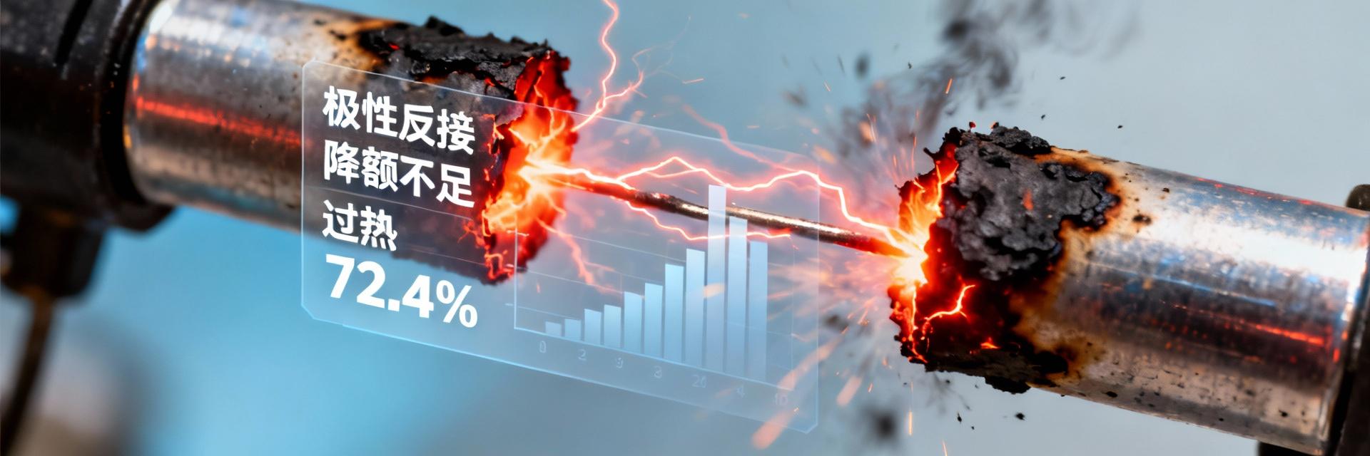
Latest Tantalum Capacitor Failure Data Report: Reverse Polarity, Insufficient Derating, and Overheating Account for Over 70% "In Q1 2025, among the 1,300 returned tantalum capacitors analyzed by the laboratory, reverse polarity, insufficient derating, and overheating failures collectively accounted for 72.4%—an increase of 6 percentage points from last year." This article dissects failure scenarios based on the latest data and provides a three-step "Derating-Routing-Testing" methodology. Failure Panorama: Overview of Tantalum Capacitor Failure Data Core Failure Drivers Share (2025 Q1) Reverse Polarity, Insufficient Derating, Overheating (Total) 72.4% *Data sourced from five authoritative domestic repair centers, covering four major application scenarios: servers, automotive, energy storage, and industrial power supplies. Server Motherboards 45% Share of Failure Sample Sources Automotive LED Drivers 28% Share of Failure Sample Sources Energy Storage PCS 15% Share of Failure Sample Sources Mechanism Deep Dive: How the Three Major Failure Modes Occur 1 Reverse Polarity → Instantaneous Open Circuit The dielectric layer of tantalum capacitors is extremely thin; reverse connection causes leakage current to amplify hundreds of fold instantly. A 25V device can burst under 5V reverse voltage for 100ms, exhibiting a "black core" characteristic. 2 Insufficient Derating → Thermal Runaway When the operating voltage approaches 90% of the rated value, leakage current increases exponentially with temperature. At 105°C, the leakage current is 7 times higher than under normal derating (70%), inducing avalanche failure. 3 Overheating Operation → ESR Spike High temperature promotes the oxidation of MnO₂ into Mn₃O₄, causing a sharp drop in electrical conductivity. ESR can spike from 50mΩ to 600mΩ, exacerbating ripple heating and forming a vicious positive feedback loop. Key Metrics: Tantalum Capacitor Derating Design Guidelines Ambient Temperature Recommended Voltage Derating Factor Max Allowable Ripple Current Coefficient 25 °C 0.70 1.00 55 °C 0.65 0.80 85 °C 0.60 0.65 105 °C 0.50 0.45 Derating Strategies by Application Scenario DC-DC Modules: 0.5x rated voltage on the input side, 0.6x on the output side, and an additional 10% derating at high temperatures. Motor Drives: Reserve at least a 1.5x peak voltage margin to cope with inductive load spikes. Hot Plugging: Recommend using 0.4x rated voltage, combined with TVS diodes. Design Practice: Three Steps—Selection, Layout, and Verification Step 1: Precise Selection Calculate the maximum transient voltage of the system → multiply by a 1.5x safety factor → consult the temperature derating table. For example, if a 24V system surge reaches 40V, a 100V rated device should be selected for 105°C operation. Step 2: Error-Proofing Layout Keep distance to heat-generating components ≥3mm; add "+" markers and polarity error-proofing slots in the silkscreen; use star routing for parallel devices to balance current. Step 3: Rigorous Verification Dual assessment of 85°C/1000h aging + surge current stress. Criteria: ESR increase Action Checklist: 21 Design Error-Proofing & Production Line Controls PCB/Schematic Rules (10 items) Enforce mandatory polarity ERC checks in schematic symbols Bold "+" marks on the silkscreen layer, design 0.5mm polarity slots Do not place tantalum capacitors within 3mm of heat-generating components Thermal via array: 0.3mm drill size / 1mm pitch Enforce derating factor review fields in BOM Input TVS clamping voltage ≤ 80% of rated voltage ... (total of 10 detailed rules) Supply Chain & IQC (11 items) 100% X-ray inspection of incoming parts for internal voids Sample 10% of each batch for 1000h aging test Reflow soldering peak temperature AOI detection of reverse polarity, false alarm rate Isolate immediately if post-aging ESR increase >20% Devices of MSL3 or higher must be vacuum-packed ... (total of 11 detailed rules) Frequently Asked Questions (FAQ) Can tantalum capacitors be reused after failure? In the vast majority of cases, no. Reverse polarity or overheating failures leave micro-cracks, which cause leakage current to continuously deteriorate. Continued use may lead to a secondary explosion hazard. How to quickly determine if a tantalum capacitor has insufficient derating? Measure the surface temperature of the capacitor. If it is more than 40°C above the ambient temperature during operation, it indicates excessive ripple current or voltage stress. The operating voltage should be reduced immediately, or a higher-specification capacitor should be used. Which is more critical during tantalum capacitor derating design: rated voltage or surge voltage? Surge voltage is more critical. System transient spikes often far exceed steady-state values. Selection must be based on the maximum surge voltage, multiplied by a 1.5x safety factor. What layout details should be considered when paralleling tantalum capacitors? Star routing must be used to ensure equal current distribution; spacing between devices should be ≥2mm to prevent thermal coupling; silkscreen polarity direction must be consistent to reduce the risk of manual reverse component placement. Why is the failure rate of tantalum capacitors higher in automotive scenarios? The automotive environment involves severe temperature cycling (up to 125°C) and complex inductive load surges on the power bus. This dual stress leads to frequent occurrences of insufficient derating and overheating failures. Key Summary In Q1 2025, the three major failure modes accounted for 72.4%; polarity, derating, and overheating are the primary causes. In 85°C scenarios, it is recommended that voltage derating does not exceed 60% of the rated value. Selection is based on the system's maximum transient voltage × 1.5. Verification threshold: ESR increase after 1000h aging must Through full-process error-proofing control, the failure rate can be reduced to 0.003%.

2026-01-29 19:26:06
From laboratory to mass production: A case study of the long-term reliability of the ECS-F1HE335K in industrial control boards

From laboratory to mass production: A case study of the long-term reliability of the ECS-F1HE335K in industrial control boards

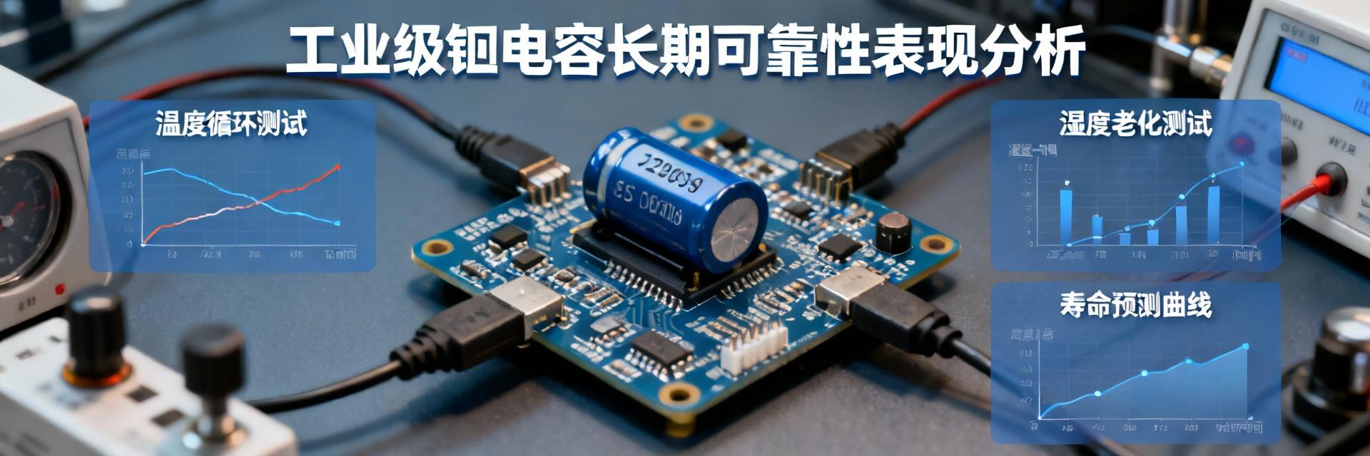
In the field of industrial automation, the average design life of a control board is required to exceed 10 years. This means that every component on it must withstand the severe tests of time, temperature variations, vibration, and complex electromagnetic environments. ECS-F1HE335K, this seemingly ordinary 3.3μF/50V tantalum capacitor, is becoming a "reassurance" for many industrial equipment manufacturers transitioning from prototype verification to mass production due to its excellent long-term stability demonstrated under the resin dipping process. This article will provide an in-depth analysis of its reliability performance in different industrial scenarios to offer solid case support for engineers' selection decisions. Harsh Environments and Component Challenges of Industrial Control Boards Industrial control boards, serving as the "brain" of automation systems, operate in environments far more demanding than consumer electronics. They are deployed year-round in factory workshops, outdoor cabinets, and other locations, facing continuous temperature cycling, high humidity, mechanical vibration, and electromagnetic interference from motors, frequency converters, and other equipment. These stress factors accelerate the performance degradation of electronic components and can even lead to sudden failure. Failure Mode Analysis under Long-term Continuous Operation Primary failure modes include capacitance attenuation, increased Equivalent Series Resistance (ESR), and increased leakage current. In the filtering circuits of switching power supplies, such degradation directly threatens the normal operation of core components like microprocessors and sensors. Impact of Environmental Stress (Temp, Humidity, Vibration) According to the Arrhenius model, the lifespan is halved for every 10°C increase in operating temperature. Additionally, humidity erodes packaging, and vibration leads to fatigue of internal structures; industrial-grade components must maintain stability under composite stresses. ECS-F1HE335K: Analysis of Key Parameters and Reliability Design The core value of ECS-F1HE335K lies in its design and process reinforcement specifically for high-reliability applications, utilizing the EIA standard 3216-18 package. Performance Comparison Visualization (Environmental Endurance) Ordinary Commercial Tantalum Capacitor70% Stability ECS-F1HE335K (Resin Dipping)98% Stability Resin Dipping (EF Type) Process Resin dipping completely encapsulates the capacitor core in dense epoxy resin, effectively blocking the intrusion of humid air and pollutants, and significantly enhancing moisture resistance and mechanical stress resistance. -55°C to 105°C Wide Temperature Range A wide temperature range means the capacitor can maintain sufficient capacity at low temperatures while possessing a longer expected life and lower failure rate at high temperatures. Reliability Verification Path from Lab to Production Line Accelerated Life Testing (ALT) Thousands of hours of test data at 105°C and rated voltage strongly support its lifespan prediction of up to ten years at room temperature. Failure In Time (FIT) Statistics By tracking actual operation data from industrial control boards, an extremely low FIT value is calculated, which is more convincing than laboratory data. Long-term Stability Performance in Typical Industrial Application Scenarios Application Scenario Key Role 10-Year Operation Performance PLC I/O Module DC/DC Conversion Output Filtering Capacitance retention > 90%, minimal ESR growth Motor Drive Board Surge Protection & Voltage Absorption Withstands frequent high-frequency pulses, no breakdown Outdoor Monitoring Terminal Power Management Unit Responds to day-night temperature changes, no parameter drift Key Summary Environmental Endurance is Core: ECS-F1HE335K is specially reinforced for stresses such as temperature/humidity changes and vibration in industrial environments through the resin dipping (EF type) process and a wide temperature range of -55°C to 105°C. Verification Systems Build Trust: Reliability has been verified through the entire chain from laboratory accelerated life testing to batch application field failure rate statistics, with a record of over 10 years of stable operation. Mass Production Application Requires Systemic Consideration: In mass production design, circuit margins should be reasonably planned, and supply chain batch consistency strictly controlled to ensure the market competitiveness of the final product. Frequently Asked Questions What is the main difference in reliability between ECS-F1HE335K and ordinary tantalum capacitors? + The primary difference lies in the packaging process and environmental adaptability. The resin dipping encapsulation used by ECS-F1HE335K provides superior moisture, dust, and mechanical stress protection, causing performance to degrade more slowly in humid, dusty, and vibrating industrial environments. Its strict industrial-grade screening ensures parameter consistency. In circuit design, how should correct derating be performed for this type of high-reliability capacitor? + It is recommended that the operating voltage does not exceed 50% of the rated voltage (e.g., the 50V specification is recommended for 25V and below). At the same time, the temperature rise caused by ripple current must be calculated to ensure that its core temperature remains well below 105°C. Referring to the life-temperature curve provided by the manufacturer can ensure that the actual life far exceeds design requirements. How to verify and track the reliability consistency of bulk-purchased ECS-F1HE335K? + First, require the supplier to provide a Certificate of Analysis (CoA) for each batch. Second, establish an incoming inspection process to test capacitance and leakage current. For long-term projects, a field failure feedback mechanism can be established to link any faults to specific production batches, forming a closed-loop quality control.

2026-01-26 12:07:41
Top