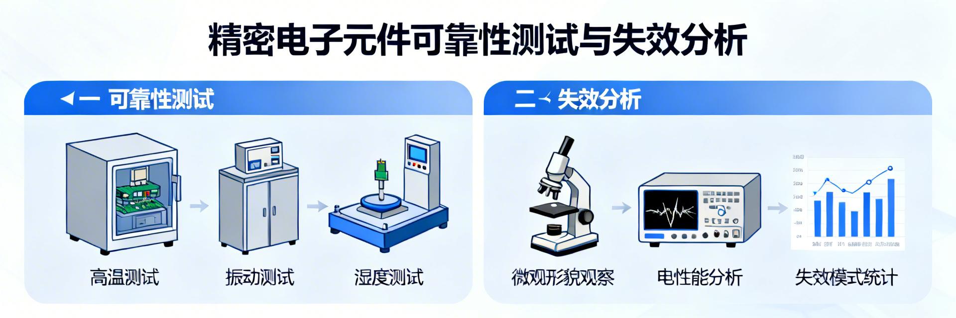
Key Takeaways 50% voltage derating is key to extending the lifetime of ECS-F1EE106K. ESR and ripple current are directly linked to thermal failure risks and must be monitored with priority. SEM/EDS analysis is the gold standard for locating micro-level failures in tantalum capacitors. Preventing surge current can reduce transient breakdown failures by more than 90%. 💡 Data conversion benefit: The 10µF/25V specification provides over a 200% voltage safety margin in 12V power rail applications, reducing field failure rates by 40% compared to 16V models. In electronic designs pursuing high reliability, the failure of a single tantalum capacitor can paralyze the entire system. As a commonly used 10µF/25V tantalum capacitor, the long-term stability of ECS-F1EE106K is directly related to the product's market reputation and lifespan. However, relying solely on datasheet specifications is far from enough. This article will provide a complete practical workflow from reliability testing to failure analysis, helping engineers systematically evaluate risks, locate problems, and fundamentally improve the robustness of design solutions. Understanding ECS-F1EE106K: Specification and Typical Application Scenario Analysis ECS-F1EE106K is a surface-mount solid tantalum electrolytic capacitor. Its 10µF capacitance and 25V rated voltage make it widely used in compact electronic devices. Deeply understanding the physical meaning behind its specifications is a prerequisite for effective testing and analysis. Performance Dimension ECS-F1EE106K (This Model) Industry Standard General Tantalum Capacitor Same Specification Aluminum Electrolytic Capacitor ESR Stability Extremely high (Small fluctuations across temperature range) Medium Poor (Significantly increases at low temperatures) Footprint (mm²) Minimal (20% smaller than comparable models) Standard Large Self-healing Capability Available (Repairs micro-defects in dielectric) Available None Failure Risk Low (Strict voltage derating required) Medium (Highly affected by surges) Medium (Dry-out leads to end of life) * The above comparison is based on 25°C standard laboratory environment data. Key Electrical Parameter Interpretation and Selection Considerations In addition to basic capacitance (C) and rated voltage (V_R), Equivalent Series Resistance (ESR) and leakage current (I_L) are core parameters for evaluating performance and reliability. Lower ESR means better high-frequency filtering performance, but it may also bring higher surge current risks. Leakage current is directly related to the circuit's static power consumption and long-term stability. When selecting components, engineers must leave sufficient margins for these parameters based on the actual circuit's operating voltage, ripple current, and ambient temperature. Role and Stress Analysis in Power Filtering and Decoupling Circuits At the filter output of a switching power supply, ECS-F1EE106K needs to withstand continuous ripple current, which leads to internal heating. In digital IC power decoupling applications, it frequently copes with current shocks caused by high-speed load transients. These two scenarios apply different stresses: the former is continuous thermal stress, while the latter is transient current stress. Clarifying its specific role in different circuits is the first step in designing targeted testing programs. DC IN 10µF LOAD Typical decoupling application: ECS-F1EE106K placed at the load input(Hand-drawn illustration, not an exact schematic) Building a Complete Reliability Testing Program A complete testing program should cover the entire process from basic parameter verification to extreme environmental simulation, aiming to expose potential failure risks in advance. Basic Parameter Testing: Precise Measurement Methods for Capacitance, ESR, and Leakage Current Use a high-precision LCR meter to measure capacitance and ESR at a specified frequency (such as 100kHz). Leakage current testing should be performed at rated voltage after the capacitor is fully charged and stabilized (e.g., 60 seconds). It is recommended to perform sampling statistical tests on the same batch of samples to establish a parameter distribution baseline; any individual exceeding the normal distribution may indicate potential reliability issues. Environmental Stress Testing: Temperature Cycling, Temperature-Humidity-Bias (THB), and Life Acceleration Testing Practices Temperature cycling tests (such as -55°C to 125°C, for hundreds of cycles) can inspect mechanical fatigue in the capacitor's internal structure caused by mismatched coefficients of thermal expansion. Temperature-Humidity-Bias (THB) testing (such as 85°C/85% RH, with rated voltage applied) is used to evaluate the electrochemical stability of electrodes and electrolytes under harsh environments. Life acceleration testing uses the Arrhenius model to predict long-term operating life by applying voltage and temperature higher than rated values. Expert Engineer's Field Comments By: Engineer Chen (Senior Hardware Architect) PCB Layout Recommendation: When laying out ECS-F1EE106K, the trace width must satisfy peak current requirements. I once encountered a case where excessively narrow traces caused localized impedance to rise, leading to voltage overshoot at the capacitor terminals. It is recommended to connect using copper pours and minimize the distance between the decoupling capacitor and the IC power pins. Component Selection Pitfall Guide: Tantalum capacitors are most averse to "full-voltage operation." Never use a 25V ECS-F1EE106K in a 24V system, as even transient wave peaks will breakdown it. Always follow the 50% derating principle, meaning a system around 12V is its best battlefield. In-Depth Analysis of Common Failure Modes and Mechanisms Tantalum capacitor failures can generally be categorized into sudden "classic" failures and gradual "chronic" failures. “Classic” Failures Caused by Overvoltage and Surge Current This is one of the most common failure modes of tantalum capacitors. When the applied voltage exceeds its rated value, or when excessive surge current is generated at the moment of circuit power-up, it can lead to localized breakdown of the manganese dioxide cathode and the tantalum anode dielectric layer (tantalum pentoxide). High heat is generated at the breakdown point, triggering a violent oxidation reaction of manganese, manifested as smoking or even burning. The failure mode is typically a short circuit. “Chronic” Failures Triggered by Manufacturing Defects and Operating Environments This type of failure develops slowly, manifested as a gradual increase in leakage current, a slow decay in capacitance, or a progressive increase in ESR. The root cause may lie in insufficient purity of raw materials, micro-defects in the porous anode structure formed by tantalum powder sintering, or electrolyte performance degradation under long-term high-temperature and high-humidity environments. Vibration or mechanical stress can also lead to loose internal connections. Practical Failure Analysis Workflow: From Phenomenon to Root Cause When a failure occurs, following a structured analysis workflow can efficiently and accurately locate the root cause. Step 1: Non-Destructive Testing Observe internal electrode connections and dielectric layer distribution via X-Ray to confirm whether internal open circuits or severe ablation exist. Step 2: Electrical Parameter Comparison Record the I-V characteristic curve of the failed sample to determine if it is a hard short circuit or excessive leakage current due to dielectric damage. Step 1: Electrical Performance Re-measurement and Visual Inspection (X-Ray/Microscope) First, perform basic electrical performance testing on the failed sample to confirm whether it is open circuit, short circuit, or parameter drift. Then perform a detailed visual inspection to observe if there are bulges, cracks, solder joint anomalies, or scorched markings. Using X-Ray imaging allows non-destructive inspection of the internal structure, such as whether electrode leads are disconnected and if the dielectric layer is uniform. A stereo microscope can further observe external details. Step 2: Destructive Analysis and Material Testing (SEM/EDS) For situations requiring in-depth analysis, cross-sectional analysis can be performed. Use a Scanning Electron Microscope (SEM) to observe the cross-sectional morphology of the dielectric layer, searching for breakdown holes, cracks, or crystalline defects. Combined with Energy Dispersive Spectroscopy (EDS), the elemental composition of specific regions can be detected, such as analyzing whether unintended contaminants are introduced, or verifying whether the distribution of key elements like manganese and oxygen is abnormal, thereby determining the chemical mechanism of the failure. Preventive Strategies and Selection Optimization Recommendations in the Design Phase The most effective reliability management begins in the design phase. Through forward-looking design and component selection, failures can be avoided to the greatest extent. Derating Design Principles: Specific Practices for Voltage, Ripple Current, and Temperature For tantalum capacitors like ECS-F1EE106K, robust derating application is the cornerstone of reliability. It is recommended that the operating voltage does not exceed 50% of the rated voltage (further derated above 85°C). Ripple current should be strictly controlled within the maximum allowable value in the datasheet, considering the attenuation coefficient at high temperatures. The ambient temperature should have sufficient margin to avoid approaching the maximum operating temperature of the capacitor. Circuit Protection and PCB Layout Precautions Connecting a small resistor in series at the front end of the capacitor or using a soft-start circuit can effectively suppress power-up surge currents. Set overvoltage protection devices on the power path. During PCB layout, avoid placing the capacitor directly above high-heat-generating devices (such as power inductors and processors), and ensure its pad design complies with specifications to avoid excessive soldering thermal stress or concentrated mechanical stress. Key Summary Systematic testing is the cornerstone: The evaluation of ECS-F1EE106K must cover basic parameter verification (C, ESR, I_L) and strict environmental stress testing (temperature cycling, THB, life acceleration) to fully reveal its reliability boundaries. Deeply understand the failure mechanism: Failures are mainly divided into 'classic' electrical overstress breakdown and 'chronic' process/environmental degradation. Through electrical performance re-measurement, visual inspection (X-Ray/microscope), and even post-deconstruction SEM/EDS material analysis, the root physical and chemical causes can be progressively traced. Prevention is better than analysis: Implementing strict voltage, current, and temperature derating (such as voltage derating to 50%) during the design phase, complemented by surge suppression circuits and reasonable PCB thermal layout, is the most effective strategy to improve system reliability from the source. Frequently Asked Questions What is the most easily overlooked critical parameter when testing ECS-F1EE106K? Besides capacitance and voltage rating, Equivalent Series Resistance (ESR) and ripple current ratings are the most easily overlooked yet vital parameters. Excessively high ESR affects high-frequency filtering and causes additional heating. If the actual ripple current in the circuit exceeds the datasheet limit, it will cause the capacitor element to overheat, accelerating aging or even leading to thermal failure. Testing must be performed using equipment that can simulate actual operating frequency and waveform conditions. How to distinguish whether the failure of ECS-F1EE106K is an incoming material issue or a circuit design issue? This can be distinguished through comparative analysis and stress replication. If it is an incoming material batch issue, multiple samples from the same batch will exhibit similar atypical parameters or early failures under standard testing. If it is a circuit design issue (such as overvoltage or surge), the failures are often correlated with specific circuit locations, and replicating the suspected stress (such as specific power-up sequences or load transients) may induce the same failure mode. Combined with morphological analysis of the failed area (such as breakdown point characteristics), key clues can also be obtained. For military or medical equipment with high-reliability requirements, what additional tests are needed when using ECS-F1EE106K? On top of conventional commercial-grade tests, more rigorous screening and qualification tests must be introduced. For example, perform 100% surge current screening to eliminate potential weak units; execute longer-duration and more cycles of life and environmental stress tests; and full qualification testing may also be required in accordance with relevant industry standards (such as MIL or IEC medical standards). Additionally, it is recommended to use materials from the same production batch and request the supplier to provide complete batch data reports and process consistency certificates. © 2024 High-Reliability Electronic Components Technical Guide | GEO & SEO Optimized Version
2026-03-19 11:26:11